Ads

Get STM32 tutorial using HAL at $10 for a limited time!

Saturday, December 26, 2015

ARM Cortex-M3 (STM32F103) Tutorial - Keil uVision IDE - Make a New Project

In this tutorial, I will explain how to make a new project for STM32F103C8 using Keil uVision IDE. STM32F103C8 is a 32-bit microcontroller produced by ST Microelectronincs Company. It use ARM Cortex-M3 CPU Core. The clock speed is up to 72MHz. It has 64Kbytes of flash memory and 20Kbytes of SRAM.


The development board for this microcontroller is quite small. It came with DIP 40 pin that fits on breadboard. It has 2 × 12-bit ADCs, 7 × timers, Up to 9 communication interface (3 × USART, 2 × I2C, 2 × SPI, 1 × CAN, 1 × USB), External Interupt, DMA.


Friday, December 25, 2015

Altium Designer Tutorial 4 - PCB Layout

In the previous tutorial, we have finished the circuit schematic. In this tutorial, I will continue to make the PCB layout. First, select menu Design → Update PCB Document to create PCB document from the schematic that has been made.

This dialog will be show, then click Execute Changes button.


You can move the component and place them on the right position. This is example of the component location.


Sunday, December 20, 2015

LCD 16x2 HD44780 Tutorial 6 - 4-bit Data Transfer

In this tutorial, I will share hoe to use 4-bit data transfer between to the LCD 16x2. This technique is useful when we want to control LCD from microcontroller, because it use less GPIO pins. 4-bit interface is only used 4 wire from D7 to D4, D3 to D0 is not used. The transfer method is high nibble first, then followed by low nibble.

This is the procedure how to use 4-bit data transfer to display 'A' character:
  1. Send command: 0b0010 xxxx (Set 4-bit data transfer).
  2. Send command: 0b0010 xxxx (high nibble function set).
  3. Send command: 0b1000 xxxx (low nibble function set).
  4. Send command: 0b0000 xxxx (high nibble display on, underline on, blinking on).
  5. Send command: 0b1111 xxxx (low nibble display on, underline on, blinking on).
  6. Send data: 0b0100 xxxx (high nibble 'A').
  7. Send data: 0b0001 xxxx (low nibble 'A').

Saturday, December 19, 2015

LCD 16x2 HD44780 Tutorial 5 - Create Custom Character

In this tutorial, I will share how to create and display custom characters on LCD 16x2. First thing you must know is that on the LCD 16x2 there are two memories that storing defined characters, CGROM and CGRAM.

CGROM is used for storing all permanent font that can be displayed by using their ASCII code. For example, if we write 0x41 then on the display will show 'A' character. CGROM memory is non-volatile and can't be modified.

CGRAM is another memory that can be used for storing user defined characters. This memory is volatile and can be modified any time. This memory can store up to 8 user defined characters. Characters that stored in CGRAM can be accessed from code 0x00 to 0x07.

This table below show character codes and character patterns for CGRAM and CGROM:


Monday, November 30, 2015

Interfacing with Parallel Port and C++ Part 1

Parallel port is one of the interface that can be found on a PC, especially on old PCs. This port is used for sending information to the printer and also known as printer port. The physical connector of parallel port is consist of 25 pins and also known as DB25 connector.


These pins can be divide to four groups:

  1. Output pins (2 - 9): Output pins is used for transmit data (8-bits) from PC to printer in parallel format (each pin is used to transmit one bit of data at a time). 
  2. Input pins (10, 11, 12, 13, 15): Input pins is used to read indicator status that received from printer.
  3. Input/Output (Bidirectional) pins (1, 14, 16, 17): These lines was used for control the flow of data.
  4. GND pins (18 - 25).
We can read or write data from or to these I/O pins by accessing their I/O address. There are three sequential I/O address space that corresponding to the parallel port pins: 0x378 (output pins), 0x379 (input pins), 0x37A (input/output pins).

Saturday, November 28, 2015

BattleBots Robot Prototype using ATmega16 and HC-05 Bluetooth


BattleBots is an American competition television series. The competition is about robot wars. Competitors design and operate remote-controlled armed and armored machines designed fight in an arena combat elimination tournament.


Sunday, November 1, 2015

Altium Designer Tutorial 3 - Circuit Schematic

In the previous tutorial, we have made the schematic symbol and component footprint. Now in this tutorial, I will continue to make circuit schematic. You can go to schematic file by double click on the project explorer.

The final schematic of the circuit is looks like this:


Monday, October 26, 2015

Altium Designer Tutorial 2 - Footprint Library

In the previous tutorial, we have created schematic component symbol. Now in this tutorial I will share how to make footprint for that component symbols.

First, go to the PCB library project. In this tutorial, I will make component footprint with wizard tools, but it is also possible to create component footprint without wizard. The advantage of wizard tools is you can make the component footprint more easy and fast. There are two type of component wizards, first is "IPC Compliant Footprint Wizard" and second is "Component Wizard". Both of them can be access from menu Tools.

For example, I will make SMD capacitor footprint using tool Component Wizard. This is the steps to do that:
  • First, select the component that you want to make, in this case is capacitor.

Sunday, October 25, 2015

Altium Designer Tutorial 1 - Schematic Library

In this tutorial, I will share how to use Altium Designer software to make a simple PCB layout. This tutorial will explain how to make the circuit schematic, PCB layout, schematic library, and PCB footprint library. This tutorial is suitable for beginner who never use Altium Designer to learn the basic function of this software.

For this tutorial, I will make PCB for simple 3.3V power supply module. After you start the Altium Designer software, go to Flie New Project to make a new Altium project. Then give name for that project, for example "power_supply_3_3_v".

On the Projects explorer, right click on the project that has been created and select Add New to Project Schematic to add a schematic file to that project. Repeat this step for add PCB file, schematic library file, and PCB library file. To rename all the files that have been created can be done by menu File Save All

Sunday, September 20, 2015

LCD 16x2 HD44780 Tutorial 4 - Character Entry Mode

In this tutorial, I will discuss about character entry mode of LCD 16x2 HD44780. There are 4 character entry mode that can be selected. So far, we have been used the default character entry mode until previous post. The entry mode is auto-incrementing the cursor address every new character is entered. It is also possible to auto-decrementing the cursor and combine with shifting the display.

This is the first entry mode or the default entry mode. To do this we can send instruction 0b00000110 to the LCD. This is the default entry mode every LCD powered on. Every new character is entered, the cursor/ DDRAM address is auto-incremented by 1. This mode is illustrated by picture below:

  1. Set cursor to 0x07 address location.
  2. Put char 'A' on 0x07 location, cursor auto-incremented to 0x08 address location.
  3. Put char 'B' on 0x08 location, cursor auto-incremented to 0x09 address location.
  4. Put char 'C' on 0x09 location, cursor auto-incremented to 0x0A address location.
  5. Return home (0x00 location).

Saturday, September 19, 2015

LCD 16x2 HD44780 Tutorial 3 - Display Address and Shifting

In previous tutorial, we have done displaying a word "AnNyeongHaSeYo!" (Hello in Korean) on LCD 16x2. In this tutorial, I will explain about addressing to DDRAM (Display Data RAM). The function of DDRAM is to store character that displayed on LCD screen. 

HD44780 LCD controller has 128 different addresses for DDRAM, although not all addresses have their own location on LCD screen. Only 80 display locations can be used to store characters. HD44780 is a LCD controller that can be used not just for 16x2 LCD size, but also for other size such as 16x4, 20x2, or 40x2. The display location for all LCD size is also same (80 location). The different is number of location that can displayed on screen. For example, on 16x2 size is only 32 location, but other location still can be used to store character, although not displayed. To displayed that, we can shift the display right or left. This is the address location of DDRAM that displayed on LCD 16x2 size every LCD power on:


Sunday, August 30, 2015

STM32F4 Discovery Tutorial 10 - PWM

In this tutorial, I will share how to use PWM on STM32F4 Discovery board. PWM (Pulse Width Modulation) is a technique for generating analog voltage (average value) by using microcontroller's digital outputs. PWM is used in DC motor speed control, servo motor control, dimming LED, audio generation and many more.


PWM signal is a modulated digital logic (0 and 1). PWM signal have a duty cycle. Duty cycle is measured in percentage. The percentage of duty cycle is calculated from time of a digital signal is on over period of time.


STM32F4 Discovery Tutorial 9 - Timer Interrupt

In this tutorial, I will share how to generate interrupt every given interval using timer on STM32F4 Discovery board. For example project, we will make orange LED toggle every 500ms interval using TIM2. In the main program we will toggle blue LED every 2500ms (blue LED toggling will not using timer interrupt, but just use delay function).

First, we write code for initialize timer. We will use TIM2. This is the block diagram for configuring the timer clock:


void TIM_INT_Init()
{
    // Enable clock for TIM2
    RCC_APB1PeriphClockCmd(RCC_APB1Periph_TIM2, ENABLE);

    // TIM2 initialization overflow every 500ms
    // TIM2 by default has clock of 84MHz
    // Here, we must set value of prescaler and period,
    // so update event is 0.5Hz or 500ms
    // Update Event (Hz) = timer_clock / ((TIM_Prescaler + 1) * 
    // (TIM_Period + 1))
    // Update Event (Hz) = 84MHz / ((4199 + 1) * (9999 + 1)) = 2 Hz
    TIM_TimeBaseInitTypeDef TIM_TimeBaseInitStruct;
    TIM_TimeBaseInitStruct.TIM_Prescaler = 4199;
    TIM_TimeBaseInitStruct.TIM_Period = 9999;
    TIM_TimeBaseInitStruct.TIM_ClockDivision = TIM_CKD_DIV1;
    TIM_TimeBaseInitStruct.TIM_CounterMode = TIM_CounterMode_Up;

    // TIM2 initialize
    TIM_TimeBaseInit(TIM2, &TIM_TimeBaseInitStruct);
    // Enable TIM2 interrupt
    TIM_ITConfig(TIM2, TIM_IT_Update, ENABLE);
    // Start TIM2
    TIM_Cmd(TIM2, ENABLE);

    // Nested vectored interrupt settings
    // TIM2 interrupt is most important (PreemptionPriority and 
    // SubPriority = 0)
    NVIC_InitTypeDef NVIC_InitStruct;
    NVIC_InitStruct.NVIC_IRQChannel = TIM2_IRQn;
    NVIC_InitStruct.NVIC_IRQChannelPreemptionPriority = 0;
    NVIC_InitStruct.NVIC_IRQChannelSubPriority = 0;
    NVIC_InitStruct.NVIC_IRQChannelCmd = ENABLE;
    NVIC_Init(&NVIC_InitStruct);
}

Saturday, August 29, 2015

STM32F4 Discovery Tutorial 8 - External Interrupt

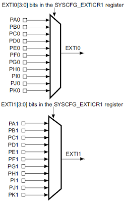
In this tutorial, I will share how to use external interrupt on STM32F4 Discovery. STM32F4 has 23 external interrupt. These external interrupt lines is consist of 2 sections. First sections (line0 to line15) is for external interrupt from GPIO pins (P0 to P15). The other section is for peripherals events (RTC, Ethernet, USB).

We can use 16 external interrupt line (line0 to line15) to detect external event from GPIO pins. Each pin from all GPIO port is connected to each external interrupt line with the same number.
  • PA0, PB0, PC0 and so on, are multiplexed to line0. So you can only configure one of these pins to connect to line0 interrupt.
  • PA0 and PA8 are multiplexed to different line. So you can configure these pins to use external interrupt at the same time. Because PA0 is connected to line0 and PA8 is connected to line8.


Sunday, July 19, 2015

STM32F4 Discovery Tutorial 7 - ADC

In this tutorial, I will share how to use ADC on STM32F4 Discovery to read analog voltage. ADC is stands for Analog to Digital Converter. Microcontrollers are digital component, so they only understand discrete/digital signals. Therefore if you want to read analog voltage that can be from various sensors, you need an ADC. STM32F407 has 3 ADC that can work independently. Every ADC have 18 channels. 16 channels are external and connected to GPIO pin. 2 channels are internal that connected to internal temperature sensor and ADC voltage reference.

When you use ADC, you can choose which ADC and its channel from this table:


Friday, July 17, 2015

Arduino Tutorial - Make Delay with Timer 0 (CTC Mode, Pooling)

In my another tutorial Make Delay with Timer 0 (CTC Mode, Pooling), I have made a delay function using timer 0 in normal mode. This time I will modify the timer mode to use CTC mode. In normal mode, timer count will count up from loaded value to overflow value. In CTC mode, timer count will count up from zero to compare match value. Compare match value is stored on compare match register (OCRx). To calculate compare match value for delay 10ms, we can use this formula OCR0A = (0.01s * 16000000Hz)/1024 = 156 = 0x9C.

After we get OCR0A value, we can use that in delay function:
// Delay 10ms with timer 0 CTC mode, pooling
void T0Delay()
{
    // Load initial count value
    TCNT0 = 0;
    // Load compare match value
    OCR0A = 0x9C;
    // Init timer mode and prescaler
    TCCR0A = (1 << WGM01);
    TCCR0B = (1 << CS02) | ( 1 << CS00);
    // Wait until timer 0 compare match
    while ((TIFR0 & (1 << OCF0A)) == 0);
    // Stop timer 0
    TCCR0B = 0;
    // Clear compare math flag
    TIFR0 = (1 << OCF0A);
}

Arduino Tutorial - Make Delay with Timer 0 (Normal Mode, Pooling)

In this tutorial, I will show you how to make a delay function with timer 0 on Arduino Uno. The delay function will generate a delay of 10ms. The settings that I used for this timer is normal mode. In this mode, timer will count from a loaded value up to timer overflow value. Loaded value for timer 0 (TCNT0) can be calculated with this formula TCNT0 = (1 + 0xFF) - (T * CLK)/N. T is the period of this timer will be overflow (0.01s), N is the prescaler, and CLK is the crystal frequency (16 MHz). The prescaler that I use is 1024. Therefore the TCNT0 value is (1 + 0xFF) - (0.01s * 16000000Hz)/1024 = 100 = 0x64.

This is the function for generating 10ms delay using timer 0:
// Delay 10ms with timer 0 normal mode, pooling
void T0Delay()
{
    // Load initial count value
    TCNT0 = 0x64;
    // Init timer mode and prescaler
    TCCR0A = 0;
    TCCR0B = (1 << CS02) | (1 << CS00);
    // Wait until timer 0 overflow
    while ((TIFR0 & (1 << TOV0)) == 0);
    // Stop timer 0
    TCCR0B = 0;
    // Clear time 0 overflow flag
    TIFR0 = (1 << TOV0);
}
In this function there is a while loop for waiting until timer 0 is overflow. Using while loop for waiting something happen is usually called pooling method. When use pooling method, CPU is not do anything and can't do other task, just wait until something happen.

Sunday, July 12, 2015

AVR ATmega Tutorial - Millis Function on AVR Microcontrollers

In this tutorial, I will make tutorial for making millis() function that will return number of millisecond since AVR microcontrollers began executing program. This function is like millis() function on Arduino. I will use ATmega16 and CodeVisionAVR for this tutorial. First, you have to make a variable that will hold the value of millisecond. I declared this variable as volatile because the value of this variable will be changed inside ISR.
// Store value of millisecond since uC started
volatile unsigned long millis_value;
Next, Setup timer 0 (or another timer if you wish) to generate interrupt every 1 ms. I am using timer 0 on CTC mode to count up from 0 to the value of OCR0 register. The prescaler that I use is 64 with 16 MHz CPU clock. To calculate the OCR0 register for 1ms compare match, we can use this formula OCRx = ((T x Fcpu) / N) - 1. Where T is the desired compare match value in second (1ms = 0.001s), Fcpu in Hz is 16,000,000 and N is prescaler (64). The OCR0 value will be 0xF9. To generate code for this settings we will use CodeWizardAVR. This is the settings for timer 0:

Saturday, June 20, 2015

LCD 16x2 HD44780 Tutorial 2 - Basic Commands and Displaying Text

In this post, I will explain how to send commands and characters data to LCD 16x2 HD44780. From the previous tutorial, we have finished building the circuit on the breadboard. When you power up this circuit, you will see a series of square only on line 1 of the display. This is the default pattern of an uninitialized LCD display. The LCD will always reset itself to this pattern when power is applied. If you not see this pattern, you can turn the resistor variable that controls the contrast of the LCD until see this pattern.


Wednesday, June 17, 2015

Using INI File for Storing Application Settings on .NET C#

In this post, I will explain INI file for storing application settings such as database connection settings. INI files are simple text file which have a basic structure of sections, properties, and values. INI file have filename extension .ini, which stands for "initialization". Every property has a value delimited by an equal sign.
property=value
Properties can be grouped into sections. The sections name appear inside square brackets. Sections is not necessary needed on every INI file.
[section]
property=value
Every line that started with a semicolon is a comment.
;This is a comment

Saturday, June 13, 2015

LCD 16x2 HD44780 Tutorial 1 - Basic Circuit

In this tutorial, I will explain about LCD 16x2 basic operation. LCD 16x2 that I will use have a Hitachi HD44780 (or compatible) controller chip. In this tutorial I will not use any microcontroller for controlling the LCD, but just use a series of switches, because it will be useful to understand the working principle of HD44780 controller chip. When you use microcontroller to drive LCD effectively, this experiment can be a benefical step to have more knowledge about HD44780 chip rather than just use existing library.


First step of this experiment is make the circuit. I will make this circuit on a breadboard. This is the circuit that I use for this experiment.

Saturday, May 16, 2015

Arduino and Ethernet Shield Tutorial - Control a LED from PC

In this tutorial, I will explain how to control a LED from PC using Arduino ethernet shield. The Arduino ethernet shield is use WIZnet W5100 ethernet chip. The advantage of using this chip over ENC28J60 is the TCP/IP stack is already implemented by hardware on this chip. With ENC chip the TCP/IP must implemented on the MCU that is interfaced to it.


This shield is also has a micro SD card socket to interfacing with a micro SD card. Arduino communicates with both W5100 and micro SD card using the SPI bus. This is on digital pins 13 (SCK), 12 (MISO), 11 (MOSI), 10 (SS for the W5100), and 4 (SS for the micro SD card). To make a program using this shield is very easy, because there is a library from Arduino both for ethernet and SD.

Tuesday, May 5, 2015

Arduino and ENC28J60 Module Tutorial - Ping Test from PC to Arduino

In this tutorial, I will explain how to use ENC28J60 ethernet module.


To use this module with Arduino, I will use EtherCard library. In this tutorial, I will make a simple code on Arduino, so a PC that connected to network can do a ping test to the Arduino. 

First thing to do is connect the ENC28J60 to Arduino using this connection:


Saturday, May 2, 2015

Java and PosgreSQL Tutorial 1 - Database Connection

In this tutorial I will share how to make an application with Java that use PostgreSQL database. I will use Netbeans IDE for this tutorial. Netbeans already has PostgreSQL library, so to use this library you can add to your project from Library folder (right click) then select Add Library. In the Add Library dialog, select PostgreSQL JDBC Driver.


Sunday, April 26, 2015

STM32F4 Discovery Tutorial 6 - USART Polling Mode

In this tutorial, I will share how to use STM32F4 USART in polling mode. STM32F4 Discovery board has 6 U(S)ART channels (USART1, USART2, USART3, UART4, UART5, and USART6). USART can be used for communication with PC or another device that use USART communication such as bluetooth module, GSM module and so much more. USART 1 and USART6 are connected to APB2 bus and able to communicate at speeds of up to 10.5 Mbit/s. USART2, USART3, UART4, UART5 are connected to APB1 bus and able to communicate at speeds of up to 5.25 Mbit/s.

To interface STM32F4 to your PC with USART, you can use either DB9 port or use USB port (Using USB to RS232 converter or USB to TTL converter). If you use DB9 port, then you must add additional electronic components like MAX232 IC to adjust voltage level.


Saturday, April 18, 2015

STM32F4 Discovery Tutorial 5 - Make Delay Using System Timer (SysTick)

In this tutorial, I’ll explain about system timer (SysTick). SysTick timer can be used to make delay function. STM32F4 has a 24-bit system timer, that counts down from RELOAD value to zero (16,777,215 to 0). The SysTick clock source is 168 MHz so 168,000,000 ticks per second. The time required to make one tick is 1 ÷ 168,000,000 ≈ 5.952 ns.

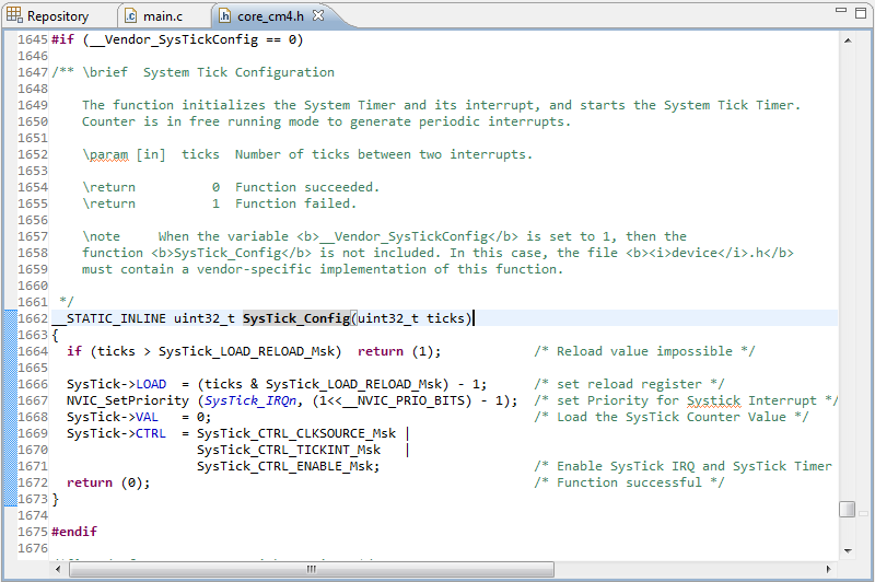
To use SysTick timer we have to call SysTick_Config function which responsible to initializes the system tick timer and its interrupt and start the system tick timer. The timer is in free running mode to generate periodical interrupts. Parameter input of SysTick_Config function is number of ticks between two interrupts (time between two interrupts). You can see SysTick_Config function in core_cm4.h.


Wednesday, April 15, 2015

C# and PostgreSQL Using Npgsql Tutorial 3 - SELECT Command

In this tutorial, I will share to you about SQL SELECT command. For me there is two technique that commonly used for read the result of SELECT command. The first technique is use NpgsqlDataReader and the second is use NpgsqlDataAdapter. This is the example code when using NpgsqlDataReader:
// Select all records form tb_music using NpgsqlDataReader.
public List<Music> selectAllRecordsUsingList()
{
    List<Music> music = new List<Music>();

    openConnection();

    try
    {
        // Create select command.
        NpgsqlCommand command = new NpgsqlCommand("SELECT * FROM " + 
            "tb_music ORDER BY id ASC", connection);

        // Prepare the command.
        command.Prepare();

        // Execute SQL command.
        NpgsqlDataReader dr = command.ExecuteReader();

        // Fill results to music list.
        while (dr.Read())
        {
            music.Add(new Music(dr.GetInt32(0), dr.GetString(1), 
                dr.GetString(2)));
        }
    }
    catch (NpgsqlException ex)
    {
        showError(ex);
    }

    closeConnection();

    return music;
}

C# and PostgreSQL Using Npgsql Tutorial 2 - INSERT, UPDATE, and DELETE Command

In this tutorial, I will share to you how to make functions for performing basic SQL command such as INSERT, UPDATE, and DELETE. For this tutorial I will add 3 more functions that needed to perform SQL basic commands (INSERT, UPDATE, and DELETE). This is the function for INSERT new record to tb_music table.
// Insert new record to tb_music.
public void insertRecord(Int32 id, String title, String artist)
{
    openConnection();

    try
    {
        // Create insert command.
        NpgsqlCommand command = new NpgsqlCommand("INSERT INTO " +
            "tb_music(id, title, artist) VALUES(:id, :title, " +
            ":artist)", connection);

        // Add paramaters.
        command.Parameters.Add(new NpgsqlParameter("id",
            NpgsqlTypes.NpgsqlDbType.Integer));
        command.Parameters.Add(new NpgsqlParameter("title",
            NpgsqlTypes.NpgsqlDbType.Varchar));
        command.Parameters.Add(new NpgsqlParameter("artist",
            NpgsqlTypes.NpgsqlDbType.Varchar));

        // Prepare the command.
        command.Prepare();

        // Add value to the paramater.
        command.Parameters[0].Value = id;
        command.Parameters[1].Value = title;
        command.Parameters[2].Value = artist;

        // Execute SQL command.
        int recordAffected = command.ExecuteNonQuery();
        if (Convert.ToBoolean(recordAffected))
        {
            showInformation("Data successfully saved!");
        }
    }
    catch (NpgsqlException ex)
    {
        showError(ex);
    }

    closeConnection();
}

Monday, April 13, 2015

C# and PostgreSQL Using Npgsql Tutorial 1 - Database Connection

In this tutorial I will share how to make an application with .NET C# that use PostgreSQL database. I am using Visual Studio 2012 for this tutorial. To use Npgsql you must download the library from here. Then add Npgsql.dll and MonoSecurity.dll to project references. References can be found in solution explorer.


After you add Npgsql.dll and MonoSecurity.dll to project references, the next step is to include Npgsql library to your source code using this code:
using Npgsql;
For this tutorial, I will share how to make connection between the application and the database. I will make a class called DatabaseHelper. This class is responsible for handling database functions such as database connection, INSERT, UPDATE, DELETE, SELECT and so on.

Wednesday, April 8, 2015

SQLite Database


SQLite is a relational database management system that written in C programming language. SQLite is stand-alone database (not a client-server database). SQLite is a popular database for local storage in application software. There are many applications that use SQLite for local storage such as web browsers. SQLite is used in web browsers for storing bookmarks, configuration, etc. SQLite is also used in Android for local apps database such as contact, notepad, dictionary, and many more. Another famous product that use SQLite can be found in here.

Tuesday, April 7, 2015

Arduino 16x2 LCD Keypad Shield

In this tutorial, I will share how to use 16x2 LCD Keypad Shield with Arduino Uno. This product is compatible with Arduino LCD library (LiquidCrystal.h). There are 5 buttons in this product (up, down, left, right, and select) that can be used for make project such as display menu items and select them with the buttons.
The 5 buttons in this product are connected to only single pin (A0), so this will save the use of pins. This technique usually called multiplexing. Multiplexing technique can be implemented with multiplexer IC such as 74153. But in this product they use a chain of resistor to do multiplexing. The buttons are connected to a chain of resistors using voltage divider technique. 


Saturday, March 28, 2015

STM32F4 Discovery Tutorial 4 - Configure Clock Using External Crystal (HSE)

From the first tutorial until this tutorial, the system clock that we use is internal RC oscillator (HSI) which the value is 16 MHz. This can be checked by using this simple code:
#include "stm32f4xx.h"

int main(void)
{
    // Update the system core clock variable 
    // according to current clock register value
    SystemCoreClockUpdate();

    while (1);
}
SystemCoreClockUpdate() function is used for update SystemCoreClock variable that store the value of current system clock. To see this variable value, we can go into debug mode. In the Variables tab, do the right click and select Add Global Variables then select the SystemCoreClock variable. After that we can step over the SystemCoreClockUpdate() by using F10. After that line is executed, the SystemCoreClock is updated to 16 MHz in Variables tab.


Sunday, March 22, 2015

Micromouse Robot

I made micromouse robot for my final project. I made this because I was so excited when I first saw this robot. This is the micromouse that make me excited. This micromouse is named Tetra and made by Kato-san. The size is even smaller compared to Tamiya mini 4 WD.


I was playing mini 4 WD when I was elementary school. Tamiya can run fast and turn in the track as it has rollers. When I first saw micromouse, there is a question came to my head. Why and how micromouse can run fast without touching the wall and can also navigate the maze to reach center of the maze? I even ever think that micromouse is controlled by a remote control, but that’s not true. The fact is micromouse has an algorithm to solve the maze. I was so excited to figure out how to make my micromouse, so I make micromouse robot for my final project. This is my micromouse.


Monday, March 16, 2015

STM32F4 Discovery Tutorial 3 - Get Input from Button

In this tutorial, I will explain how to configure pin as an input from button. I will use user button which connected to PA0.

First, make new project called button or whatever you want. If you don’t know how to make a new project, you can learn from tutorial 2. After that don’t forget to include the library for this project.
#include "stm32f4xx.h"
#include "stm32f4xx_rcc.h"
#include "stm32f4xx_gpio.h"
Every time you want to use GPIO, you must configure RCC (Reset and Clock Control) for each GPIO.
// Enable peripheral clock to GPIOA module
RCC_AHB1PeriphClockCmd(RCC_AHB1Periph_GPIOA, ENABLE);
// Enable peripheral clock to GPIOD module
RCC_AHB1PeriphClockCmd(RCC_AHB1Periph_GPIOD, ENABLE);
GPIO_InitTypeDef is a struct which used for input initialization value for GPIO.
// This is struct for configure GPIO
GPIO_InitTypeDef GPIO_InitStruct;

Thursday, February 19, 2015

STM32F4 Discovery Tutorial 2 - Simple LED Blinking

In this tutorial, I will explain how to make a simple blinking LED on STM32F4 Discovery. First, you have to make new project from menu Project  New Project. Give the project name and select folder for that project. 


Next, select model based on chip and then search for STM32F407VG.

Tuesday, February 17, 2015

STM32F4 Discovery Tutorial 1 - Getting Started with STM32F4 Discovery and CooCox IDE

In this tutorial I will explain how to configure CooCox IDE and ARM GCC toolchain for programming STM32F4 Discovery.


First, you have to download and install driver for STM32F4 Discovery from here. After that, you have to download ARM GCC toolchain and install it. All default parameters are okay. Finally, you have to download CooCox IDE (You must register first).

For the first time using CooCox you have to configure ARM GCC toolchain from menu Project → Select Toolchain Path and browse to location of \bin folder of ARM GCC toolchain and press OK.


Now, it is ready to start coding.