Ads

Get STM32 tutorial using HAL at $10 for a limited time!

Tuesday, July 19, 2016

Verilog Tutorial 3 - ModelSim - BCD Incrementor

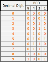
Binary Coded Decimal (BCD) is a class of binary encoding of decimal numbers where each decimal digit is represented by a fixed number of bits, usually four or eight[1]. BCD is also called "8421" encoding. This is the truth table of BCD encoding, where each decimal digits is represented by its corresponding 4-bit binary value:


For example, 16810 (101010002) is represented as "0001 0110 1000" in BCD format. In this tutorial, I will implementing a digital circuit for adds 1 to a number in BCD format. The BCD format is three-digit decimal number (12-bit). For example, after incrementing, "0010 0101 1001" (25910) becomes "0010 0110 0000" (26010).

This is the top level schematic for three-digit BCD incrementor. This circuit is actually consist of three 4-bit incrementor module. 4-bit incrementor has input signal of BCD number and output signal of incremented BCD number. There is also a carry output signal that give indication when an incremented BCD number rollover (from 910 (10012) to 010 (00002)). In the three-digit incrementor circuit, this carry signal is used for give a signal to the next 4-bit incrementor module to increment the digit.

Sunday, July 17, 2016

Verilog Tutorial 2 - ModelSim - Dual Priority Encoder

A priority encoder is a circuit or algorithm that compresses multiple binary inputs into a smaller number of outputs[1]. In priority encoder, if two or more inputs are given at the same time, the input having the highest priority will take precedence. This is the four-request priority encoder truth table from FPGA Prototyping by Verilog Example book by Pong P. Chu.


You can learn the code implementation of that priority encoder from that book. In this tutorial, I will implement a dual priority encoder from suggested experiment on chapter 3 of this book. A dual priority encoder returns the code of the highest and second-highest priority request. The input is 12-bit signal and the outputs are the first and second priority codes, which are 4-bit binary codes of the highest and second-highest priority request.

Saturday, July 16, 2016

Verilog Tutorial 1 - ModelSim - Multifunction Barrel Shifter

A barrel shifter is a digital circuit that can shift a data word by a specified number of bits without use of any sequential logic, only pure combinational logic[1]. There are 3 type of bitwise shift operation: logical shift, arithmetic shift, and circular shift (rotate). We can shift the data to the left as well as to the right. The barrel shifter in this tutorial is a multifunction barrel shifter that can perform left or right circular shift. The basic barrel shifter in this tutorial is based on this book: FPGA Prototyping by Verilog Example by Pong P. Chu. You can also learn the basic of Verilog language from this book.

The multifunction barrel shifter in this tutorial is actually a suggested experiment from chapter 3 of the book. There are 2 design that will be implemented in this tutorial. The first design is using 1 rotate-left circuit, 1 rotate-right circuit, and one 2-to-1 multiplexer to select the desired result. The top level schematic of the first design is like this:


The second design is implemented using 1 rotate-left shifter with pre- and post- reversing circuit. The reversing circuit either pass the original input or reverses the input bitwise. For example, if the input is a7,a6,a5,a4,a3,a2,a1,a0 then the reversed result become a0,a1,a2,a3,a4,a5,a6,a7. The top level schematic of the second design is like this:

Friday, July 1, 2016

ARM Cortex-M3 (STM32F103) Tutorial - Incremental Rotary Encoder

Rotary encoder can be used for several application such as digital volume control, DC motor position sensor, etc. Rotary encoder is an electro-mechanical device that converts the angular position to an analog or digital code.


There are two type of rotary encoder: absolute and incremental. Absolute rotary encoder produce unique digital code for each distinct angle of the shaft. Incremental rotary encoder produce two square waves usually in quadrature output (channel A and B). The quadrature means that the output pulses of channel A and B are 90 degree out of phase.