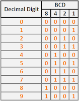
Binary Coded Decimal (BCD) is a class of binary encoding of decimal numbers where each decimal digit is represented by a fixed number of bits, usually four or eight[1]. BCD is also called "8421" encoding. This is the truth table of BCD encoding, where each decimal digits is represented by its corresponding 4-bit binary value:
For example, 16810 (101010002) is represented as "0001 0110 1000" in BCD format. In this tutorial, I will implementing a digital circuit for adds 1 to a number in BCD format. The BCD format is three-digit decimal number (12-bit). For example, after incrementing, "0010 0101 1001" (25910) becomes "0010 0110 0000" (26010).
This is the top level schematic for three-digit BCD incrementor. This circuit is actually consist of three 4-bit incrementor module. 4-bit incrementor has input signal of BCD number and output signal of incremented BCD number. There is also a carry output signal that give indication when an incremented BCD number rollover (from 910 (10012) to 010 (00002)). In the three-digit incrementor circuit, this carry signal is used for give a signal to the next 4-bit incrementor module to increment the digit.

This is the code for 4-bit incrementor using behavioral description:


You can download the project file for this circuit from my repository. This tutorial is based on FPGA Prorotyping by Verilog Example book by Pong P. Chu. This book is recommended for learning FPGA through practical example.
References:
[1] https://en.wikipedia.org/wiki/Binary-coded_decimal

For example, 16810 (101010002) is represented as "0001 0110 1000" in BCD format. In this tutorial, I will implementing a digital circuit for adds 1 to a number in BCD format. The BCD format is three-digit decimal number (12-bit). For example, after incrementing, "0010 0101 1001" (25910) becomes "0010 0110 0000" (26010).
This is the top level schematic for three-digit BCD incrementor. This circuit is actually consist of three 4-bit incrementor module. 4-bit incrementor has input signal of BCD number and output signal of incremented BCD number. There is also a carry output signal that give indication when an incremented BCD number rollover (from 910 (10012) to 010 (00002)). In the three-digit incrementor circuit, this carry signal is used for give a signal to the next 4-bit incrementor module to increment the digit.

This is the code for 4-bit incrementor using behavioral description:
// bcd_incrementer.v
module bcd_incrementer
    (
        input wire [3:0] in,
        input wire en,
        output reg [3:0] out,
        output reg carry
    );

    // Body
    always @*
    begin
        out = in;
        carry = 1'b0;
        case ({en, in[3:0]})
            5'b10000: out = 4'b0001;
            5'b10001: out = 4'b0010;
            5'b10010: out = 4'b0011;
            5'b10011: out = 4'b0100;
            5'b10100: out = 4'b0101;
            5'b10101: out = 4'b0110;
            5'b10110: out = 4'b0111;
            5'b10111: out = 4'b1000;
            5'b11000: out = 4'b1001;
            5'b11001:
                    begin
                        out = 4'b0000;
                        carry = 1'b1;
                    end
        endcase
    end

endmodule
This is the code for top module of three-digit BCD incrementor:
// top.v
module top
    (
        input wire [11:0] in,
        input wire en,
        output wire [11:0] out,
        output wire ovf
    );

    // Signal declaration
    wire c1, c2;

    // Body
    bcd_incrementer bcd_incrementer_digit_1_unit
        (.in(in[3:0]), .en(en), .out(out[3:0]), .carry(c1));

    bcd_incrementer bcd_incrementer_digit_2_unit
        (.in(in[7:4]), .en(c1), .out(out[7:4]), .carry(c2));

    bcd_incrementer bcd_incrementer_digit_3_unit
        (.in(in[11:8]), .en(c2), .out(out[11:8]), .carry(ovf));

endmodule
This is the code for verify the circuit operation:
// top_tb.v
`timescale 1 ns/ 10 ps

module top_tb;
    // Signal declaration
    reg [11:0] in_test;
    reg en_test;
    wire [11:0] out_test;
    wire ovf_test;

    // Instantiate the circuit under test
    top uut (.in(in_test), .en(en_test), .out(out_test), .ovf(ovf_test));

    // Test vector generator
    initial
    begin
        en_test = 1'b0;

        in_test = 12'b000000000000; // 000
        # 200;
        in_test = 12'b000000000011; // 003
        # 200;
        in_test = 12'b000000100011; // 023
        # 200;
        in_test = 12'b000100100011; // 123
        # 200;
        in_test = 12'b000100101001; // 129
        # 200;
        in_test = 12'b000110010011; // 193
        # 200;
        in_test = 12'b100100100011; // 923
        # 200;
        in_test = 12'b000010011001; // 099
        # 200;
        in_test = 12'b100100001001; // 909
        # 200;
        in_test = 12'b100110010000; // 990
        # 200;
        in_test = 12'b100110011001; // 999
        # 200;

        en_test = 1'b1;

        in_test = 12'b000000000000; // 000
        # 200;
        in_test = 12'b000000000011; // 003
        # 200;
        in_test = 12'b000000100011; // 023
        # 200;
        in_test = 12'b000100100011; // 123
        # 200;
        in_test = 12'b000100101001; // 129
        # 200;
        in_test = 12'b000110010011; // 193
        # 200;
        in_test = 12'b100100100011; // 923
        # 200;
        in_test = 12'b000010011001; // 099
        # 200;
        in_test = 12'b100100001001; // 909
        # 200;
        in_test = 12'b100110010000; // 990
        # 200;
        in_test = 12'b100110011001; // 999
        # 200;

        // Stop simulation
        $stop;
    end

endmodule
This is the waveform result from three-digit BCD incrementor:

You can download the project file for this circuit from my repository. This tutorial is based on FPGA Prorotyping by Verilog Example book by Pong P. Chu. This book is recommended for learning FPGA through practical example.
References:
[1] https://en.wikipedia.org/wiki/Binary-coded_decimal
This is a great way to start investing for your future, and if you are not sure of what you want to do, then you can get a free Gold IRA guide and get all of the help you need to make sure that you have a great investment portfolio.
ReplyDeleteEmbedded System course in Noida
ReplyDelete
ReplyDeleteEmbedded Systems Training Course in Delhi
Embedded Systems Training Course in Gurgaon
ReplyDeleteEmbedded Systems Training in Noida
ReplyDeleteEmbedded Systems Training Institute in Noida
ReplyDeleteYou can get benefit from this project file for this circuit from my repository. This wyze coupons is recommended for avail wonderful discounts
ReplyDeleteI recommend everyone to read this blog as it has some of the best data science content you will find. The best part is that the writer presented the information in an engaging and engaging way. Each line gives you something new to learn, and that says a lot about the quality of the information presented here.
ReplyDeleteKickstart your career by enrolling in this Data Science Certification Course in Chennai
"I'm genuinely impressed by the quality of your blog post. The content was presented in a clear and concise manner, making it easy to understand and follow. Thank you for sharing your expertise and enriching the reader's experience."
ReplyDeleteTop Engineering & Agriculture College in Andhra Pradesh
"InstaBuyJ is your one-stop shop for all things mobile repair! With an unbeatable selection of top-quality tools, fixing your device has never been easier. From screen replacements to battery swaps, they've got the tools you need to get the job done right. Plus, their user-friendly website and lightning-fast shipping make ordering a breeze. Don't let a broken phone slow you down – shop InstaBuyJ and get back to peak performance in no time!"
ReplyDeleteEnquiry Now -mobile repairing tools buy online
AC Scrap Buyer in Bangalore
ReplyDeleteVery informative, thanks for sharing this article.
ReplyDeleteIf you are looking for a Digital marketing class in Hyderabad, Look no further, Whitescholars is one of the best academy providing Digital Marketing course in Hyderabad.
digital marketing course in hyderabad
Very informative, thanks for sharing this article. embedded systems mini project
ReplyDelete