In this tutorial, I will explain about LCD 16x2 basic operation. LCD 16x2 that I will use have a Hitachi HD44780 (or compatible) controller chip. In this tutorial I will not use any microcontroller for controlling the LCD, but just use a series of switches, because it will be useful to understand the working principle of HD44780 controller chip. When you use microcontroller to drive LCD effectively, this experiment can be a benefical step to have more knowledge about HD44780 chip rather than just use existing library.

First step of this experiment is make the circuit. I will make this circuit on a breadboard. This is the circuit that I use for this experiment.
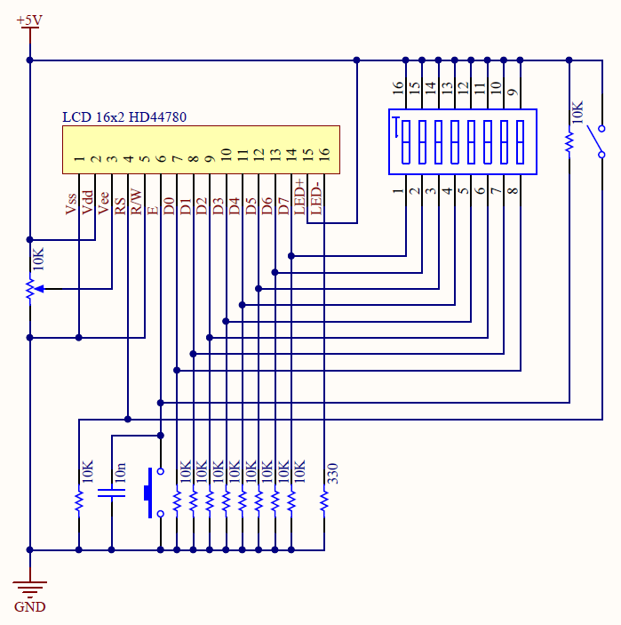
LCD HD44780 has 16 pins:
- Pin 1 and 2 are Vss and Vdd pin for this LCD module. Vss pin should be connected to 0V supply or ground. Vdd pin should be connected to positive supply (usually +5V).
- Pin 3 is Contrast (Vee) pin. This pin is usually connected using a variable resistor that create a voltage divider circuit. the more voltage inputed to this pin, the contrast is more low, otherwise the contrast is more high. If you don't have a variable resistor you can also connect this pin to GND through a 10KΩ resistor.
- Pin 4 is Register Select (RS) pin. If this pin is low, then the LCD will only accept command, otherwise if the pin is high, then the LCD will accept data.
- Pin 5 is Read/Write (R/W) pin. This pin has to be low in order to write command or character data to its register. To read character data from its register, this pin has to be high.
- Pin 6 is Enable (E) pin. This pin is used to initiate the actual transfer of commands or character data between module and data lines. When writing to the module, data is transferred only when falling edge of this signal. When reading from the module, data will available after rising edge of this signal and remain available until this signal falls to low again.
- Pin 7 to 14 are data bus lines (D0 to D7). Data can be transferred either as single byte (8-bit) or two nibbles (4-bit). When using 4-bit mode only D4 to D7 are used. 4-bit mode is useful when using microcontroller, because it is use fewer GPIO pins.
- Pin 15 and 16 is Vcc and GND pin for LCD backlight. You can connect this pins to power and ground through a 330Ω resistor.
This is how I made this circuit on my breadboard.

And next?
ReplyDelete