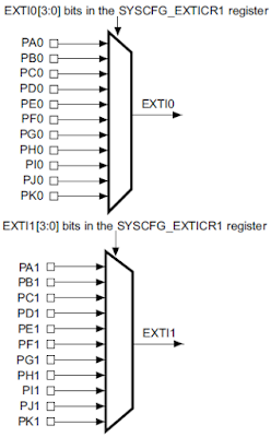
In this tutorial, I will share how to use external interrupt on STM32F4 Discovery. STM32F4 has 23 external interrupt. These external interrupt lines is consist of 2 sections. First sections (line0 to line15) is for external interrupt from GPIO pins (P0 to P15). The other section is for peripherals events (RTC, Ethernet, USB).
We can use 16 external interrupt line (line0 to line15) to detect external event from GPIO pins. Each pin from all GPIO port is connected to each external interrupt line with the same number.
- PA0, PB0, PC0 and so on, are multiplexed to line0. So you can only configure one of these pins to connect to line0 interrupt.
- PA0 and PA8 are multiplexed to different line. So you can configure these pins to use external interrupt at the same time. Because PA0 is connected to line0 and PA8 is connected to line8.
For interrupt handlers, STM32F4 has only 7 interrupt handlers for handling external interrupt from line0 to line15.
Only external interrupt from line0 to line4 that have own IRQ handler. Line5 to line9 and line10 to line15 have same IRQ handler.
Another thing that we have to configure when using interrupt on STM32F4 is NVIC (Nested Vector Interrupt Controller). The function of NVIC is for configure which interrupt is more important and for enable or disable interrupt. It support up to 256 different interrupt vectors. A lower priority value indicates a higher priority interrupt.
This is example code how to use external interrupt on PA0 (user button on STM32F4 Discovery) as interrupt source for toggling orange LED (PD13).
#include "stm32f4xx.h"
#include "stm32f4xx_rcc.h"
#include "stm32f4xx_gpio.h"
#include "stm32f4xx_exti.h"
#include "stm32f4xx_syscfg.h"
#include "misc.h"
#include "clock.h"
#include "delay.h"

void EXTI_Init(void)
{
    // Clock for GPIOA
    RCC_AHB1PeriphClockCmd(RCC_AHB1Periph_GPIOA, ENABLE);
    // Clock for SYSCFG
    RCC_APB2PeriphClockCmd(RCC_APB2Periph_SYSCFG, ENABLE);

    // GPIOA initialization as an input from user button (GPIOA0)
    GPIO_InitTypeDef GPIO_InitStruct;
    GPIO_InitStruct.GPIO_Mode = GPIO_Mode_IN;
    GPIO_InitStruct.GPIO_OType = GPIO_OType_PP;
    GPIO_InitStruct.GPIO_Pin = GPIO_Pin_0;
    GPIO_InitStruct.GPIO_PuPd = GPIO_PuPd_DOWN;
    GPIO_InitStruct.GPIO_Speed = GPIO_Speed_2MHz;
    GPIO_Init(GPIOA, &GPIO_InitStruct);

    // Selects the GPIOA pin 0 used as external interrupt source
    SYSCFG_EXTILineConfig(EXTI_PortSourceGPIOA, EXTI_PinSource0);

    // External interrupt settings
    EXTI_InitTypeDef EXTI_InitStruct;
    EXTI_InitStruct.EXTI_Line = EXTI_Line0;
    EXTI_InitStruct.EXTI_LineCmd = ENABLE;
    EXTI_InitStruct.EXTI_Mode = EXTI_Mode_Interrupt;
    EXTI_InitStruct.EXTI_Trigger = EXTI_Trigger_Rising;
    EXTI_Init(&EXTI_InitStruct);

    // Nested vectored interrupt settings
    NVIC_InitTypeDef NVIC_InitStruct;
    NVIC_InitStruct.NVIC_IRQChannel = EXTI0_IRQn;
    NVIC_InitStruct.NVIC_IRQChannelCmd = ENABLE;
    // EXTI0_IRQn has Most important interrupt
    NVIC_InitStruct.NVIC_IRQChannelPreemptionPriority = 0x00;
    NVIC_InitStruct.NVIC_IRQChannelSubPriority = 0x00;
    NVIC_Init(&NVIC_InitStruct);
}

void EXTI0_IRQHandler(void)
{
    // Checks whether the interrupt from EXTI0 or not
    if (EXTI_GetITStatus(EXTI_Line0))
    {
        // Toggle orange LED (GPIO13)
        GPIO_ToggleBits(GPIOD, GPIO_Pin_13);

        // Clears the EXTI line pending bit
        EXTI_ClearITPendingBit(EXTI_Line0);
    }
}

int main(void)
{
    // Set clock to 168MHz
    CLOCK_SetClockTo168MHz();

    // Delay initialization
    DELAY_Init();

    // External interrupt initialization
    EXTI_Init();

    // Clock for GPIOD
    RCC_AHB1PeriphClockCmd(RCC_AHB1Periph_GPIOD, ENABLE);

    // GPIOD initialization as an output for orange LED (GPIOD13)
    // and blue LED (GPIOD15)
    GPIO_InitTypeDef GPIO_InitStruct;
    GPIO_InitStruct.GPIO_Mode = GPIO_Mode_OUT;
    GPIO_InitStruct.GPIO_OType = GPIO_OType_PP;
    GPIO_InitStruct.GPIO_Pin = GPIO_Pin_13 | GPIO_Pin_15;
    GPIO_InitStruct.GPIO_PuPd = GPIO_PuPd_NOPULL;
    GPIO_InitStruct.GPIO_Speed = GPIO_Speed_2MHz;
    GPIO_Init(GPIOD, &GPIO_InitStruct);

    while (1)
    {
        // Toggle blue LED (GPIO15)
        GPIO_ToggleBits(GPIOD, GPIO_Pin_15);
        // Delay 5s
        DELAY_Ms(5000);
    }
}


Please share misc.h file; thanks in advance
ReplyDeleteDid you use CooCox IDE and GCC toolchain? If yes, the misc.h file is already included. You can select in the CoIDE Repository http://pasteboard.co/lojfORiO5.png
Delete