Ads

Get STM32 tutorial using HAL at $10 for a limited time!

Thursday, June 2, 2016

ARM Cortex-M3 (STM32F103) Project - DSP Audio Effect

In this project, I made a simple real-time DSP (Digital Signal Processing) project using ARM Cortex-M3 (STM32F013C8). The signal processed in this project is audio signal that come from electronic devices through 3.5mm audio jack. The audio signal is processed using STM32F103C8 microcontroller.


There are 3 simple audio effect that implemented in this project. These effects are low pass filter, pitch up, and pitch down. The audio output from this microcontroller is sent to an active speaker. This is block diagram of this system:


Tuesday, May 24, 2016

VHDL Tutorial - Xilinx ISE - Make A New Project for Digital Circuits Simulation

In this article, I will share about HDL (Hardware Description Language) and Xilinx ISE simulator. HDL is used for design digital circuits. There are 2 type of HDL that commonly used, VHDL and Verilog. VHDL syntax is like Pascal language, while Verilog is like C language. HDL has differences with traditional programming language such as Pascal and C. In traditional programming language, all statements always executed sequentially. In HDL, there are statements that can be executed concurrently. HDL can be used for designing a digital ASIC or programming an FPGA.


FPGA (Field Programmable Gate Array) is consists of many basic digital circuit blocks. This circuit block is usually called LUT. FPGA can be used for implement flexible digital circuits, because FPGA is like microcontroller that can be programmed using a hardware programmer. On a FPGA, we can create any digital circuits from basic combinational circuits such as adder, decoder, multiplexer up to a complex system like a microcontroller. We can create a full function microcontroller such as AVR ATmega inside a FPGA. FPGA is also used for simulation when prototyping a digital IC before go to the custom ASIC development process. There are 2 commonly used FPGA, Altera and Xilinx. These FPGA has an IDE, for Altera is Altera Quartus and for Xilinx is Xilinx ISE.


ASIC (Application Specific Integrated Circuit) is an IC that has a specific function (not flexible like FPGA). ASIC can be an analog, digital, mixed-signal, or RF IC. The process of creating an ASIC is quite complex. The process is begin from the design, synthesis, routing, fabrication, and testing. This complete and detail process can be learned from microelectronics lecture. For your information, there are several software used for design ASIC such as Synopsys, MentorGraphics, and Cadence. These software are called EDA (Electronic Design Automation) software.

Monday, April 25, 2016

ARM Cortex-M3 (STM32F103) Tutorial - SPI Master

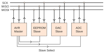
In this tutorial, I will explain about SPI communication protocol and how to use it on STM32F103 microcontroller. SPI (Serial Peripheral Interface) is a synchronous serial communication protocol. With SPI, in addition to transmitting and receiving lines, there is a third line that used for clock line. Each slave devices also has a chip select (enable) pin. These pin is used for activate the slave devices. So, to use SPI, we need 2 wire for data lines (MOSI, MISO), 1 wire for clock line, and 1 wire per device for chip select line. MOSI (Master Out Slave In) is used for data transfer from master device to slave device. MISO (Master In Slave Out) is used for data transfer from slave device to master device.


SPI communication is different from other serial communication especially on data transfer. There are no concept like transmit and receive data, but there is a data trading concept. When data trading occurs, the data bits in master register is traded with the data bits in slave register on every clock from master (one data bit per clock tick).

Saturday, April 23, 2016

ARM Cortex-M3 (STM32F103) Tutorial - LCD 16x2 Library

In this tutorial, I will share about LCD 16x2 library. With this library, you can easily use LCD 16x2 with STM32F103 microcontroller. This library contain 2 file: lcd16x2.h and lcd16x2.c files. If you want to know the more detail how the LCD 16x2 works, you can see this tutorial.


Saturday, April 16, 2016

ARM Cortex-M3 (STM32F103) Tutorial - FreeRTOS - Task

In this tutorial, I will share how use an RTOS on STM32F103 microcontroller. I use FreeRTOS for this tutorial. RTOS is usually needs when an embedded system must responds to an event within a strictly defined time.


In this tutorial, I will make RTOS task with 3 LED that blinks at different frequency. First thing to do is to download FreeRTOS library. The next step is to make a new project in Keil uVision and setup the configuration for using FreeRTOS on STM32F103.

Thursday, March 17, 2016

ARM Cortex-M3 (STM32F103) Tutorial - I2C Master

In this tutorial, I will explain about I2C protocol and how to use it on STM32F103 microcontroller. I2C (Inter-Integrated Circuit) or sometimes called TWI (Two Wire Interface) is a synchronous serial protocol that only need 2 wire for communication. These wire are SCL for clock line and SDA for data line. Using I2C bus, you can connect devices like temperature sensor, EEPROM, RTC, etc (up to 112 device) just using two wire (plus GND wire). For accessing these device, I2C use 7-bit address. Theoretically 7-bit address space allows 128 addresses, however some addresses are reserved for special purpose. Thus, only 112 address can be used. There is also special method to use I2C with 10-bit address.


I2C is multi-master and multi-slave bus. I2C bus can consists of one or more master device, but only one master device can have an access to I2C bus each time. To communicate with a slave device, master is responsible for sending clock to the slave device. Clock signal is always generated by master. I2C drivers are open-drain, means that they can pull the signal low, but can't drive it high. On each signal line (SCL and SDA) must have a pull-up resistor to restore the signal high when no device is asserting it low.