Ads

Get STM32 tutorial using HAL at $10 for a limited time!

Showing posts with label STM32F4 Discovery. Show all posts

Sunday, August 30, 2015

STM32F4 Discovery Tutorial 10 - PWM

In this tutorial, I will share how to use PWM on STM32F4 Discovery board. PWM (Pulse Width Modulation) is a technique for generating analog voltage (average value) by using microcontroller's digital outputs. PWM is used in DC motor speed control, servo motor control, dimming LED, audio generation and many more.


PWM signal is a modulated digital logic (0 and 1). PWM signal have a duty cycle. Duty cycle is measured in percentage. The percentage of duty cycle is calculated from time of a digital signal is on over period of time.


STM32F4 Discovery Tutorial 9 - Timer Interrupt

In this tutorial, I will share how to generate interrupt every given interval using timer on STM32F4 Discovery board. For example project, we will make orange LED toggle every 500ms interval using TIM2. In the main program we will toggle blue LED every 2500ms (blue LED toggling will not using timer interrupt, but just use delay function).

First, we write code for initialize timer. We will use TIM2. This is the block diagram for configuring the timer clock:


void TIM_INT_Init()
{
    // Enable clock for TIM2
    RCC_APB1PeriphClockCmd(RCC_APB1Periph_TIM2, ENABLE);

    // TIM2 initialization overflow every 500ms
    // TIM2 by default has clock of 84MHz
    // Here, we must set value of prescaler and period,
    // so update event is 0.5Hz or 500ms
    // Update Event (Hz) = timer_clock / ((TIM_Prescaler + 1) * 
    // (TIM_Period + 1))
    // Update Event (Hz) = 84MHz / ((4199 + 1) * (9999 + 1)) = 2 Hz
    TIM_TimeBaseInitTypeDef TIM_TimeBaseInitStruct;
    TIM_TimeBaseInitStruct.TIM_Prescaler = 4199;
    TIM_TimeBaseInitStruct.TIM_Period = 9999;
    TIM_TimeBaseInitStruct.TIM_ClockDivision = TIM_CKD_DIV1;
    TIM_TimeBaseInitStruct.TIM_CounterMode = TIM_CounterMode_Up;

    // TIM2 initialize
    TIM_TimeBaseInit(TIM2, &TIM_TimeBaseInitStruct);
    // Enable TIM2 interrupt
    TIM_ITConfig(TIM2, TIM_IT_Update, ENABLE);
    // Start TIM2
    TIM_Cmd(TIM2, ENABLE);

    // Nested vectored interrupt settings
    // TIM2 interrupt is most important (PreemptionPriority and 
    // SubPriority = 0)
    NVIC_InitTypeDef NVIC_InitStruct;
    NVIC_InitStruct.NVIC_IRQChannel = TIM2_IRQn;
    NVIC_InitStruct.NVIC_IRQChannelPreemptionPriority = 0;
    NVIC_InitStruct.NVIC_IRQChannelSubPriority = 0;
    NVIC_InitStruct.NVIC_IRQChannelCmd = ENABLE;
    NVIC_Init(&NVIC_InitStruct);
}

Saturday, August 29, 2015

STM32F4 Discovery Tutorial 8 - External Interrupt

In this tutorial, I will share how to use external interrupt on STM32F4 Discovery. STM32F4 has 23 external interrupt. These external interrupt lines is consist of 2 sections. First sections (line0 to line15) is for external interrupt from GPIO pins (P0 to P15). The other section is for peripherals events (RTC, Ethernet, USB).

We can use 16 external interrupt line (line0 to line15) to detect external event from GPIO pins. Each pin from all GPIO port is connected to each external interrupt line with the same number.
  • PA0, PB0, PC0 and so on, are multiplexed to line0. So you can only configure one of these pins to connect to line0 interrupt.
  • PA0 and PA8 are multiplexed to different line. So you can configure these pins to use external interrupt at the same time. Because PA0 is connected to line0 and PA8 is connected to line8.


Sunday, July 19, 2015

STM32F4 Discovery Tutorial 7 - ADC

In this tutorial, I will share how to use ADC on STM32F4 Discovery to read analog voltage. ADC is stands for Analog to Digital Converter. Microcontrollers are digital component, so they only understand discrete/digital signals. Therefore if you want to read analog voltage that can be from various sensors, you need an ADC. STM32F407 has 3 ADC that can work independently. Every ADC have 18 channels. 16 channels are external and connected to GPIO pin. 2 channels are internal that connected to internal temperature sensor and ADC voltage reference.

When you use ADC, you can choose which ADC and its channel from this table:


Sunday, April 26, 2015

STM32F4 Discovery Tutorial 6 - USART Polling Mode

In this tutorial, I will share how to use STM32F4 USART in polling mode. STM32F4 Discovery board has 6 U(S)ART channels (USART1, USART2, USART3, UART4, UART5, and USART6). USART can be used for communication with PC or another device that use USART communication such as bluetooth module, GSM module and so much more. USART 1 and USART6 are connected to APB2 bus and able to communicate at speeds of up to 10.5 Mbit/s. USART2, USART3, UART4, UART5 are connected to APB1 bus and able to communicate at speeds of up to 5.25 Mbit/s.

To interface STM32F4 to your PC with USART, you can use either DB9 port or use USB port (Using USB to RS232 converter or USB to TTL converter). If you use DB9 port, then you must add additional electronic components like MAX232 IC to adjust voltage level.


Saturday, April 18, 2015

STM32F4 Discovery Tutorial 5 - Make Delay Using System Timer (SysTick)

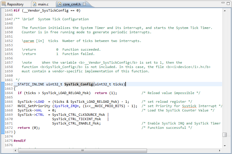
In this tutorial, I’ll explain about system timer (SysTick). SysTick timer can be used to make delay function. STM32F4 has a 24-bit system timer, that counts down from RELOAD value to zero (16,777,215 to 0). The SysTick clock source is 168 MHz so 168,000,000 ticks per second. The time required to make one tick is 1 ÷ 168,000,000 ≈ 5.952 ns.

To use SysTick timer we have to call SysTick_Config function which responsible to initializes the system tick timer and its interrupt and start the system tick timer. The timer is in free running mode to generate periodical interrupts. Parameter input of SysTick_Config function is number of ticks between two interrupts (time between two interrupts). You can see SysTick_Config function in core_cm4.h.


Saturday, March 28, 2015

STM32F4 Discovery Tutorial 4 - Configure Clock Using External Crystal (HSE)

From the first tutorial until this tutorial, the system clock that we use is internal RC oscillator (HSI) which the value is 16 MHz. This can be checked by using this simple code:
#include "stm32f4xx.h"

int main(void)
{
    // Update the system core clock variable 
    // according to current clock register value
    SystemCoreClockUpdate();

    while (1);
}
SystemCoreClockUpdate() function is used for update SystemCoreClock variable that store the value of current system clock. To see this variable value, we can go into debug mode. In the Variables tab, do the right click and select Add Global Variables then select the SystemCoreClock variable. After that we can step over the SystemCoreClockUpdate() by using F10. After that line is executed, the SystemCoreClock is updated to 16 MHz in Variables tab.


Monday, March 16, 2015

STM32F4 Discovery Tutorial 3 - Get Input from Button

In this tutorial, I will explain how to configure pin as an input from button. I will use user button which connected to PA0.

First, make new project called button or whatever you want. If you don’t know how to make a new project, you can learn from tutorial 2. After that don’t forget to include the library for this project.
#include "stm32f4xx.h"
#include "stm32f4xx_rcc.h"
#include "stm32f4xx_gpio.h"
Every time you want to use GPIO, you must configure RCC (Reset and Clock Control) for each GPIO.
// Enable peripheral clock to GPIOA module
RCC_AHB1PeriphClockCmd(RCC_AHB1Periph_GPIOA, ENABLE);
// Enable peripheral clock to GPIOD module
RCC_AHB1PeriphClockCmd(RCC_AHB1Periph_GPIOD, ENABLE);
GPIO_InitTypeDef is a struct which used for input initialization value for GPIO.
// This is struct for configure GPIO
GPIO_InitTypeDef GPIO_InitStruct;

Thursday, February 19, 2015

STM32F4 Discovery Tutorial 2 - Simple LED Blinking

In this tutorial, I will explain how to make a simple blinking LED on STM32F4 Discovery. First, you have to make new project from menu Project  New Project. Give the project name and select folder for that project. 


Next, select model based on chip and then search for STM32F407VG.

Tuesday, February 17, 2015

STM32F4 Discovery Tutorial 1 - Getting Started with STM32F4 Discovery and CooCox IDE

In this tutorial I will explain how to configure CooCox IDE and ARM GCC toolchain for programming STM32F4 Discovery.


First, you have to download and install driver for STM32F4 Discovery from here. After that, you have to download ARM GCC toolchain and install it. All default parameters are okay. Finally, you have to download CooCox IDE (You must register first).

For the first time using CooCox you have to configure ARM GCC toolchain from menu Project → Select Toolchain Path and browse to location of \bin folder of ARM GCC toolchain and press OK.


Now, it is ready to start coding.