Ads

Get STM32 tutorial using HAL at $10 for a limited time!

Showing posts with label ARM Cortex-M. Show all posts

Friday, July 1, 2016

ARM Cortex-M3 (STM32F103) Tutorial - Incremental Rotary Encoder

Rotary encoder can be used for several application such as digital volume control, DC motor position sensor, etc. Rotary encoder is an electro-mechanical device that converts the angular position to an analog or digital code.


There are two type of rotary encoder: absolute and incremental. Absolute rotary encoder produce unique digital code for each distinct angle of the shaft. Incremental rotary encoder produce two square waves usually in quadrature output (channel A and B). The quadrature means that the output pulses of channel A and B are 90 degree out of phase.

Thursday, June 23, 2016

ARM Cortex-M3 (STM32F103) Project - 16 Point FFT Audio Spectrum Analyzer

This project is the application of FFT algorithm from my previous post. I made an audio spectrum analyzer project using ARM Cortex-M3 (STM32F013C8) and LED matrix 8x8. I used 16 point FFT. 16 point FFT will produce 16 point frequency spectrum. I only display the frequency spectrum from index 1 to 8 on LED matrix 8x8. Index 0 of frequency spectrum (DC signal) is not displayed. Index 9 to 15 of frequency spectrum (symmetrical frequency) is also not displayed.


My audio sampling rate is 35.15kHz, but the frequency sampling of FFT sample is 35.15kHz/2=17.5kHz. So, the maximum frequency domain signals that can be displayed is up to 8.75kHz (Nyquist's theorem) and the resolution is 8.75kHz/81kHz.

Monday, June 20, 2016

ARM Cortex-M3 (STM32F103) Project - 32 Point DFT Audio Spectrum Analyzer

In this project, I made an audio spectrum analyzer project using ARM Cortex-M3 (STM32F013C8) and LCD 16x2. This project is the application of the real DFT algorithm from my previous post. I used 32 point real DFT for this project. 32 point DFT will transform 32 samples of time domain signal to 17 point frequency domain signal. The first point of frequency domain signal is DC. I will only display AC part (16 point) of frequency domain signal, which is from index 1 to 17 into 16 columns of LCD 16x2.


My audio sampling rate is 35.15kHz. So, the maximum frequency domain signals that can be displayed is up to 17.5kHz (Nyquist's theorem) and the resolution is 17.5kHz/161kHz.

The circuit for this project is same with the circuit for my simple audio effect project. The only differences is the LCD 16x2 and there is no dip switch circuit. You can see the detail about this circuit on this post. For the LCD, I used the custom character feature to create 8 type of bar graph. If you want to learn how to create custom char on LCD 16x2, you can see this tutorial.

Thursday, June 2, 2016

ARM Cortex-M3 (STM32F103) Project - DSP Audio Effect

In this project, I made a simple real-time DSP (Digital Signal Processing) project using ARM Cortex-M3 (STM32F013C8). The signal processed in this project is audio signal that come from electronic devices through 3.5mm audio jack. The audio signal is processed using STM32F103C8 microcontroller.


There are 3 simple audio effect that implemented in this project. These effects are low pass filter, pitch up, and pitch down. The audio output from this microcontroller is sent to an active speaker. This is block diagram of this system:


Monday, April 25, 2016

ARM Cortex-M3 (STM32F103) Tutorial - SPI Master

In this tutorial, I will explain about SPI communication protocol and how to use it on STM32F103 microcontroller. SPI (Serial Peripheral Interface) is a synchronous serial communication protocol. With SPI, in addition to transmitting and receiving lines, there is a third line that used for clock line. Each slave devices also has a chip select (enable) pin. These pin is used for activate the slave devices. So, to use SPI, we need 2 wire for data lines (MOSI, MISO), 1 wire for clock line, and 1 wire per device for chip select line. MOSI (Master Out Slave In) is used for data transfer from master device to slave device. MISO (Master In Slave Out) is used for data transfer from slave device to master device.


SPI communication is different from other serial communication especially on data transfer. There are no concept like transmit and receive data, but there is a data trading concept. When data trading occurs, the data bits in master register is traded with the data bits in slave register on every clock from master (one data bit per clock tick).

Saturday, April 23, 2016

ARM Cortex-M3 (STM32F103) Tutorial - LCD 16x2 Library

In this tutorial, I will share about LCD 16x2 library. With this library, you can easily use LCD 16x2 with STM32F103 microcontroller. This library contain 2 file: lcd16x2.h and lcd16x2.c files. If you want to know the more detail how the LCD 16x2 works, you can see this tutorial.


Saturday, April 16, 2016

ARM Cortex-M3 (STM32F103) Tutorial - FreeRTOS - Task

In this tutorial, I will share how use an RTOS on STM32F103 microcontroller. I use FreeRTOS for this tutorial. RTOS is usually needs when an embedded system must responds to an event within a strictly defined time.


In this tutorial, I will make RTOS task with 3 LED that blinks at different frequency. First thing to do is to download FreeRTOS library. The next step is to make a new project in Keil uVision and setup the configuration for using FreeRTOS on STM32F103.

Thursday, March 17, 2016

ARM Cortex-M3 (STM32F103) Tutorial - I2C Master

In this tutorial, I will explain about I2C protocol and how to use it on STM32F103 microcontroller. I2C (Inter-Integrated Circuit) or sometimes called TWI (Two Wire Interface) is a synchronous serial protocol that only need 2 wire for communication. These wire are SCL for clock line and SDA for data line. Using I2C bus, you can connect devices like temperature sensor, EEPROM, RTC, etc (up to 112 device) just using two wire (plus GND wire). For accessing these device, I2C use 7-bit address. Theoretically 7-bit address space allows 128 addresses, however some addresses are reserved for special purpose. Thus, only 112 address can be used. There is also special method to use I2C with 10-bit address.


I2C is multi-master and multi-slave bus. I2C bus can consists of one or more master device, but only one master device can have an access to I2C bus each time. To communicate with a slave device, master is responsible for sending clock to the slave device. Clock signal is always generated by master. I2C drivers are open-drain, means that they can pull the signal low, but can't drive it high. On each signal line (SCL and SDA) must have a pull-up resistor to restore the signal high when no device is asserting it low.


Monday, February 29, 2016

ARM Cortex-M3 (STM32F103) Tutorial - 4x4 Matrix Keypad

Embedded system applications usually require large number of buttons connected (ex. calculator, cell phone). Keypad is one of the input device that commonly used in embedded system that require large number of buttons. 4x4 matrix keypad have 16 buttons. We can connect this buttons directly to GPIO pin, but it will eat up precious GPIO pin (If we have 16 buttons, then we need 16 GPIO pins). To avoid this trouble, keypad use technique that will save GPIO pin. In this technique, buttons are connected in a matrix (row/column) style.


The internal connection of the buttons in 4x4 matrix keypad is like this:


Sunday, January 31, 2016

ARM Cortex-M3 (STM32F103) Tutorial - Unipolar Stepper Motor

In this tutorial, I will share how control a unipolar stepper motor using STM32F103 microcontroller. If you don't know the basic of the stepper motor, I suggest you to read this article first. To control a stepper motor from microcontroller, we can't directly drive it with GPIO pins because GPIO pins have maximum current that can sink or source from it. To overcome this problem, we can use driver circuit. The driver circuit for unipolar stepper motor can be built by using 4 transistors to drive large current every 4 wires of a stepper motor. It also can be built with ULN2003 IC. This is the circuit for driving a unipolar stepper motor from microcontroller by using ULN2003 IC:


In this tutorial, I will use 28BYJ-48 stepper motor. This motor is very cheap and it also comes with driver module based on ULN2003 IC. This motor runs with 5V supply and has gear inside. The gear reduction ratio is approximately 64:1. If you search from internet, other people say that the gear reduction ratio is actually 63.68395:1.


Sunday, January 10, 2016

ARM Cortex-M3 (STM32F103) Tutorial - System Timer - Delay Function

In this tutorial, I will share how to use system timer (SysTick) for making delay functions. SysTick is a basic countdown timer. SysTick can be used by an operating system to ease porting from another platform. SysTick can be polled by software or can be configured to generate an interrupt. To use SysTick we can reload a value to the reload value register. SysTick reload value register supports value between 0 - 0x00FFFFFF (24-bit).

SysTick can be configured through the 4 registers:


Saturday, January 2, 2016

ARM Cortex-M3 (STM32F103) Tutorial - GPIO - Read Push Button/Switch

In this tutorial, I will explain how to use STM32F103 GPIO peripheral for read input from push button. GPIO (General Purpose Input Output) on STM32F103 can be configure to 4 different modes (input mode, output mode, analog input mode, alternate function mode). For read input from push button, we need to configure GPIO in digital input mode.


STM32F013 has 3 input mode (digital input): input with internal pull-up, input with internal pull-down, and input floating. The logic voltage of STM32 microcontroller is 3.3V, so the logic voltage for GPIO input pins is also 3.3V, but there are several pins that have 5V tolerant. So, we can input 5V logic level to this 5V tolerant input pins. This table below shows I/O voltage level on STM32F103 input pins.

Friday, January 1, 2016

ARM Cortex-M3 (STM32F103) Tutorial - GPIO - Control LED On/Off

In this tutorial, I will explain how to use STM32F103 GPIO peripheral for controlling a LED. GPIO (General Purpose Input Output) on STM32F103 can be configure to 4 different modes (input mode, output mode, analog input mode, alternate function mode). For controlling LED on/off from GPIO, we need to configure GPIO in output mode.


There are 2 output modes on STM32F103. Their modes are output open drain and output push-pull. The logic voltage of STM32F103 is 3.3V, so their port bit output voltage is 3.3V. This is the characteristic of I/O port bit when configured as output mode:


Saturday, December 26, 2015

ARM Cortex-M3 (STM32F103) Tutorial - Keil uVision IDE - Make a New Project

In this tutorial, I will explain how to make a new project for STM32F103C8 using Keil uVision IDE. STM32F103C8 is a 32-bit microcontroller produced by ST Microelectronincs Company. It use ARM Cortex-M3 CPU Core. The clock speed is up to 72MHz. It has 64Kbytes of flash memory and 20Kbytes of SRAM.


The development board for this microcontroller is quite small. It came with DIP 40 pin that fits on breadboard. It has 2 × 12-bit ADCs, 7 × timers, Up to 9 communication interface (3 × USART, 2 × I2C, 2 × SPI, 1 × CAN, 1 × USB), External Interupt, DMA.


Sunday, August 30, 2015

STM32F4 Discovery Tutorial 10 - PWM

In this tutorial, I will share how to use PWM on STM32F4 Discovery board. PWM (Pulse Width Modulation) is a technique for generating analog voltage (average value) by using microcontroller's digital outputs. PWM is used in DC motor speed control, servo motor control, dimming LED, audio generation and many more.


PWM signal is a modulated digital logic (0 and 1). PWM signal have a duty cycle. Duty cycle is measured in percentage. The percentage of duty cycle is calculated from time of a digital signal is on over period of time.


STM32F4 Discovery Tutorial 9 - Timer Interrupt

In this tutorial, I will share how to generate interrupt every given interval using timer on STM32F4 Discovery board. For example project, we will make orange LED toggle every 500ms interval using TIM2. In the main program we will toggle blue LED every 2500ms (blue LED toggling will not using timer interrupt, but just use delay function).

First, we write code for initialize timer. We will use TIM2. This is the block diagram for configuring the timer clock:


void TIM_INT_Init()
{
    // Enable clock for TIM2
    RCC_APB1PeriphClockCmd(RCC_APB1Periph_TIM2, ENABLE);

    // TIM2 initialization overflow every 500ms
    // TIM2 by default has clock of 84MHz
    // Here, we must set value of prescaler and period,
    // so update event is 0.5Hz or 500ms
    // Update Event (Hz) = timer_clock / ((TIM_Prescaler + 1) * 
    // (TIM_Period + 1))
    // Update Event (Hz) = 84MHz / ((4199 + 1) * (9999 + 1)) = 2 Hz
    TIM_TimeBaseInitTypeDef TIM_TimeBaseInitStruct;
    TIM_TimeBaseInitStruct.TIM_Prescaler = 4199;
    TIM_TimeBaseInitStruct.TIM_Period = 9999;
    TIM_TimeBaseInitStruct.TIM_ClockDivision = TIM_CKD_DIV1;
    TIM_TimeBaseInitStruct.TIM_CounterMode = TIM_CounterMode_Up;

    // TIM2 initialize
    TIM_TimeBaseInit(TIM2, &TIM_TimeBaseInitStruct);
    // Enable TIM2 interrupt
    TIM_ITConfig(TIM2, TIM_IT_Update, ENABLE);
    // Start TIM2
    TIM_Cmd(TIM2, ENABLE);

    // Nested vectored interrupt settings
    // TIM2 interrupt is most important (PreemptionPriority and 
    // SubPriority = 0)
    NVIC_InitTypeDef NVIC_InitStruct;
    NVIC_InitStruct.NVIC_IRQChannel = TIM2_IRQn;
    NVIC_InitStruct.NVIC_IRQChannelPreemptionPriority = 0;
    NVIC_InitStruct.NVIC_IRQChannelSubPriority = 0;
    NVIC_InitStruct.NVIC_IRQChannelCmd = ENABLE;
    NVIC_Init(&NVIC_InitStruct);
}

Saturday, August 29, 2015

STM32F4 Discovery Tutorial 8 - External Interrupt

In this tutorial, I will share how to use external interrupt on STM32F4 Discovery. STM32F4 has 23 external interrupt. These external interrupt lines is consist of 2 sections. First sections (line0 to line15) is for external interrupt from GPIO pins (P0 to P15). The other section is for peripherals events (RTC, Ethernet, USB).

We can use 16 external interrupt line (line0 to line15) to detect external event from GPIO pins. Each pin from all GPIO port is connected to each external interrupt line with the same number.
  • PA0, PB0, PC0 and so on, are multiplexed to line0. So you can only configure one of these pins to connect to line0 interrupt.
  • PA0 and PA8 are multiplexed to different line. So you can configure these pins to use external interrupt at the same time. Because PA0 is connected to line0 and PA8 is connected to line8.


Sunday, July 19, 2015

STM32F4 Discovery Tutorial 7 - ADC

In this tutorial, I will share how to use ADC on STM32F4 Discovery to read analog voltage. ADC is stands for Analog to Digital Converter. Microcontrollers are digital component, so they only understand discrete/digital signals. Therefore if you want to read analog voltage that can be from various sensors, you need an ADC. STM32F407 has 3 ADC that can work independently. Every ADC have 18 channels. 16 channels are external and connected to GPIO pin. 2 channels are internal that connected to internal temperature sensor and ADC voltage reference.

When you use ADC, you can choose which ADC and its channel from this table:


Sunday, April 26, 2015

STM32F4 Discovery Tutorial 6 - USART Polling Mode

In this tutorial, I will share how to use STM32F4 USART in polling mode. STM32F4 Discovery board has 6 U(S)ART channels (USART1, USART2, USART3, UART4, UART5, and USART6). USART can be used for communication with PC or another device that use USART communication such as bluetooth module, GSM module and so much more. USART 1 and USART6 are connected to APB2 bus and able to communicate at speeds of up to 10.5 Mbit/s. USART2, USART3, UART4, UART5 are connected to APB1 bus and able to communicate at speeds of up to 5.25 Mbit/s.

To interface STM32F4 to your PC with USART, you can use either DB9 port or use USB port (Using USB to RS232 converter or USB to TTL converter). If you use DB9 port, then you must add additional electronic components like MAX232 IC to adjust voltage level.


Saturday, April 18, 2015

STM32F4 Discovery Tutorial 5 - Make Delay Using System Timer (SysTick)

In this tutorial, I’ll explain about system timer (SysTick). SysTick timer can be used to make delay function. STM32F4 has a 24-bit system timer, that counts down from RELOAD value to zero (16,777,215 to 0). The SysTick clock source is 168 MHz so 168,000,000 ticks per second. The time required to make one tick is 1 ÷ 168,000,000 ≈ 5.952 ns.

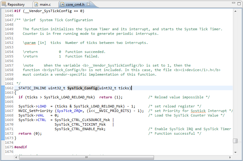
To use SysTick timer we have to call SysTick_Config function which responsible to initializes the system tick timer and its interrupt and start the system tick timer. The timer is in free running mode to generate periodical interrupts. Parameter input of SysTick_Config function is number of ticks between two interrupts (time between two interrupts). You can see SysTick_Config function in core_cm4.h.