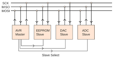
In this tutorial, I will explain about SPI communication protocol and how to use it on STM32F103 microcontroller. SPI (Serial Peripheral Interface) is a synchronous serial communication protocol. With SPI, in addition to transmitting and receiving lines, there is a third line that used for clock line. Each slave devices also has a chip select (enable) pin. These pin is used for activate the slave devices. So, to use SPI, we need 2 wire for data lines (MOSI, MISO), 1 wire for clock line, and 1 wire per device for chip select line. MOSI (Master Out Slave In) is used for data transfer from master device to slave device. MISO (Master In Slave Out) is used for data transfer from slave device to master device.
SPI communication is different from other serial communication especially on data transfer. There are no concept like transmit and receive data, but there is a data trading concept. When data trading occurs, the data bits in master register is traded with the data bits in slave register on every clock from master (one data bit per clock tick).
SPI communication is different from other serial communication especially on data transfer. There are no concept like transmit and receive data, but there is a data trading concept. When data trading occurs, the data bits in master register is traded with the data bits in slave register on every clock from master (one data bit per clock tick).


