Parallel port is one of the interface that can be found on a PC, especially on old PCs. This port is used for sending information to the printer and also known as printer port. The physical connector of parallel port is consist of 25 pins and also known as DB25 connector.
These pins can be divide to four groups:
- Output pins (2 - 9): Output pins is used for transmit data (8-bits) from PC to printer in parallel format (each pin is used to transmit one bit of data at a time).
- Input pins (10, 11, 12, 13, 15): Input pins is used to read indicator status that received from printer.
- Input/Output (Bidirectional) pins (1, 14, 16, 17): These lines was used for control the flow of data.
- GND pins (18 - 25).
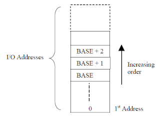
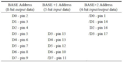
The 0x378 address can be defined as BASE address of parallel port I/O address. The two other addresses is defined by BASE+1 (0x379) and BASE+2 (0x37A). Writing to BASE address will output 8 bits of data to parallel port output pins. The BASE+1 address is read only. It is used for read data that come from printer/other external device. The BASE+2 address is input/output address, so we can read or write data from or to this address.
The picture below show the mapping between parallel port pins and each bit location in the I/O address space.
For summary, parallel port use three I/O addresses for transfer data through port's interface. Each address control one byte of data, however, for two I/O address, several data bits are unused and and few other bits are inverted internally by port circuity. The first I/O address is used to output data only, the second address is used to input data only, and the last address can be used to both input and output data.
Referenced from:
- Interfacing with C++ Programming Real-World Applications by Jayantha Katupitiya and Kim Bentley.


No comments :
Post a Comment