In this article, I will share about HDL (Hardware Description Language) and Xilinx ISE simulator. HDL is used for design digital circuits. There are 2 type of HDL that commonly used, VHDL and Verilog. VHDL syntax is like Pascal language, while Verilog is like C language. HDL has differences with traditional programming language such as Pascal and C. In traditional programming language, all statements always executed sequentially. In HDL, there are statements that can be executed concurrently. HDL can be used for designing a digital ASIC or programming an FPGA.
FPGA (Field Programmable Gate Array) is consists of many basic digital circuit blocks. This circuit block is usually called LUT. FPGA can be used for implement flexible digital circuits, because FPGA is like microcontroller that can be programmed using a hardware programmer. On a FPGA, we can create any digital circuits from basic combinational circuits such as adder, decoder, multiplexer up to a complex system like a microcontroller. We can create a full function microcontroller such as AVR ATmega inside a FPGA. FPGA is also used for simulation when prototyping a digital IC before go to the custom ASIC development process. There are 2 commonly used FPGA, Altera and Xilinx. These FPGA has an IDE, for Altera is Altera Quartus and for Xilinx is Xilinx ISE.
ASIC (Application Specific Integrated Circuit) is an IC that has a specific function (not flexible like FPGA). ASIC can be an analog, digital, mixed-signal, or RF IC. The process of creating an ASIC is quite complex. The process is begin from the design, synthesis, routing, fabrication, and testing. This complete and detail process can be learned from microelectronics lecture. For your information, there are several software used for design ASIC such as Synopsys, MentorGraphics, and Cadence. These software are called EDA (Electronic Design Automation) software.
In this tutorial, I will focus only on design and simulation of digital circuits using Xilinx software. In this tutorial, I will create a very simple digital circuit, nand gate using VHDL language. First thing to do is make a new project in Xilinx software. Go to menu File → New Project then, give name for the project, for example "nand_gate".
After that, this dialog below is for selecting FPGA board and other configuration. For now, we can use default configuration because I will not implement the circuit on FPGA board, but only run in simulator. Then click next to go to the next dialog and then click finish.
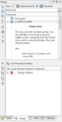
On the design explorer window, change the view from implementation to simulation.
Go to menu Project → New Source to create a source code. Select VHDL module and give name for that source file. Then click next to go to the next dialog and then click finish.
On the text editor, we can start to make VHDL code for implementing nand gate. This is the code for nand gate:
library IEEE;
use IEEE.STD_LOGIC_1164.ALL;

entity nandg is
    port(
        a, b: in std_logic;
        f: out std_logic
    );
end nandg;

architecture nandg_arch of nandg is
begin
    f <= not (a and b);
end nandg_arch;
After that, we must create another file called test bench for testing that circuit. Go to menu Project → New Source then add new VHDL Test Bench. Then click next to go to the next dialog and then click finish.This is VHDL code for test nand gate:
library IEEE;
use IEEE.STD_LOGIC_1164.ALL;

entity nandg_tb is
end nandg_tb;

architecture nandg_tb_arch of nandg_tb is
    signal test_a, test_b: std_logic;
    signal test_f: std_logic;
begin
    uut: entity work.nandg(nandg_arch)
        port map(a=>test_a, b=>test_b, f=>test_f);

    process
    begin
        test_a <= '0';
        test_b <= '0';
        wait for 200ns;
        test_a <= '0';
        test_b <= '1';
        wait for 200ns;
        test_a <= '1';
        test_b <= '0';
        wait for 200ns;
        test_a <= '1';
        test_b <= '1';
        wait for 200ns;
    end process;
end nandg_tb_arch;
In this test bench, I test the nand gate with its truth table. This is the truth table for nand gate:To test the code, we can go to the design explorer, click the source file, then click Behavioral Check Syntax button. If there is no error on VHDL code, then green check icon will appear.
To run the simulation, we can click the Simulate Behavioral Model button. New application called ISim will be running and show the waveform for test vector that we created on test bench source code.
You can check and verify this waveform with truth table of nand gate. You can download this project file from my repository.


No comments :
Post a Comment