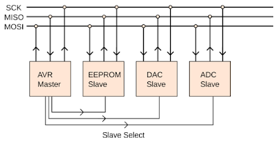
In this tutorial, I will explain about SPI communication protocol and how to use it on STM32F103 microcontroller. SPI (Serial Peripheral Interface) is a synchronous serial communication protocol. With SPI, in addition to transmitting and receiving lines, there is a third line that used for clock line. Each slave devices also has a chip select (enable) pin. These pin is used for activate the slave devices. So, to use SPI, we need 2 wire for data lines (MOSI, MISO), 1 wire for clock line, and 1 wire per device for chip select line. MOSI (Master Out Slave In) is used for data transfer from master device to slave device. MISO (Master In Slave Out) is used for data transfer from slave device to master device.
SPI communication is different from other serial communication especially on data transfer. There are no concept like transmit and receive data, but there is a data trading concept. When data trading occurs, the data bits in master register is traded with the data bits in slave register on every clock from master (one data bit per clock tick).
You can think SPI is like shift registers. There are two shift registers, one in master device and another in slave device. Each input of shift register is connected to the output of the other through MOSI and MISO lines that they form a ring.

This image illustrated bit trading from maser to slave. Master register contain data 0xFF and slave register contain data 0x00. After one clock tick, the master is left with seven of its original bits and the first one that's come in from the slave, and vice versa. After a total of eight clock ticks, all eight bits of each byte have traded place.
Sometimes not all data byte come from slave or sent to slave is meaningful. This happen because probably slave device has not received any command yet, so the data in slave register is not meaningful. Another case, if we just want to take data from slave, but don't want to send any command to slave, we can place dummy byte on master register and then give eight clock ticks for trading with data bits in slave register.
This is example of SPI protocol timing diagram:

On the image above, we know that to communicate to slave device, the slave select pin is activated (active low). On every rising edge of clock tick, the data is sampled. We also can sample data on falling edge of clock, this setting usually can be configured depending on the feature of the hardware SPI that you use. In this example, master is send data byte 0x53 to slave and then slave send sata byte 0x46 to master. The order of the data sent is LSB first, but it also can MSB first depending on the configuration.
In this tutorial, I will share how to use SPI on STM32F103 microcontroller as a master and for the slave I will use Arduino. We can send data char '1' from SPI master device to turn on LED blinking on Arduino. To turn off LED blinking, we can send '0' from master device. Master also can read LED blinking status (off/on) from Arduino by sending '?' first, then read the LED blinking status which returns 0 or 1.
This is the code for Arduino as an I2C slave:
You can see the full code from my repository.
Referenced from:
- Make: AVR Programming by Elliot Williams.

SPI communication is different from other serial communication especially on data transfer. There are no concept like transmit and receive data, but there is a data trading concept. When data trading occurs, the data bits in master register is traded with the data bits in slave register on every clock from master (one data bit per clock tick).
You can think SPI is like shift registers. There are two shift registers, one in master device and another in slave device. Each input of shift register is connected to the output of the other through MOSI and MISO lines that they form a ring.

This image illustrated bit trading from maser to slave. Master register contain data 0xFF and slave register contain data 0x00. After one clock tick, the master is left with seven of its original bits and the first one that's come in from the slave, and vice versa. After a total of eight clock ticks, all eight bits of each byte have traded place.
Sometimes not all data byte come from slave or sent to slave is meaningful. This happen because probably slave device has not received any command yet, so the data in slave register is not meaningful. Another case, if we just want to take data from slave, but don't want to send any command to slave, we can place dummy byte on master register and then give eight clock ticks for trading with data bits in slave register.
This is example of SPI protocol timing diagram:

On the image above, we know that to communicate to slave device, the slave select pin is activated (active low). On every rising edge of clock tick, the data is sampled. We also can sample data on falling edge of clock, this setting usually can be configured depending on the feature of the hardware SPI that you use. In this example, master is send data byte 0x53 to slave and then slave send sata byte 0x46 to master. The order of the data sent is LSB first, but it also can MSB first depending on the configuration.
In this tutorial, I will share how to use SPI on STM32F103 microcontroller as a master and for the slave I will use Arduino. We can send data char '1' from SPI master device to turn on LED blinking on Arduino. To turn off LED blinking, we can send '0' from master device. Master also can read LED blinking status (off/on) from Arduino by sending '?' first, then read the LED blinking status which returns 0 or 1.
This is the code for Arduino as an I2C slave:
#define LED_PIN  9

volatile uint8_t led_blink = 0;

ISR(SPI_STC_vect)
{
    uint8_t data_byte = SPDR;

    switch (data_byte)
    {
        case '0':
            led_blink = 0;
            SPDR = 0;
        break;
        case '1':
            led_blink = 1;
            SPDR = 0;
        break;
        case '?':
            // Place LED blinking status in SPDR register for next transfer
            SPDR = led_blink;
        break;
    }
}

void setup()
{
    pinMode(LED_PIN, OUTPUT);

    // Set MISO pin as output
    pinMode(MISO, OUTPUT);
    // Turn on SPI in slave mode
    SPCR |= (1 << SPE);
    // Turn on interrupt
    SPCR |= (1 << SPIE);
}

void loop()
{
    // If LED blink status is on, then blink LED for 250ms
    if (led_blink == 1)
    {
        digitalWrite(LED_PIN, HIGH);
        delay(250);
        digitalWrite(LED_PIN, LOW);
        delay(250);
    }
    else if (led_blink == 0)
    {
        digitalWrite(LED_PIN, LOW);
    }
}
For the SPI master on STM32F103, I have wrote the code, that consist of several functions:
void SPIx_Init()
{
    // Initialization struct
    SPI_InitTypeDef SPI_InitStruct;
    GPIO_InitTypeDef GPIO_InitStruct;

    // Step 1: Initialize SPI
    RCC_APB2PeriphClockCmd(SPIx_RCC, ENABLE);
    SPI_InitStruct.SPI_BaudRatePrescaler = SPI_BaudRatePrescaler_128;
    SPI_InitStruct.SPI_CPHA = SPI_CPHA_1Edge;
    SPI_InitStruct.SPI_CPOL = SPI_CPOL_Low;
    SPI_InitStruct.SPI_DataSize = SPI_DataSize_8b;
    SPI_InitStruct.SPI_Direction = SPI_Direction_2Lines_FullDuplex;
    SPI_InitStruct.SPI_FirstBit = SPI_FirstBit_MSB;
    SPI_InitStruct.SPI_Mode = SPI_Mode_Master;
    SPI_InitStruct.SPI_NSS = SPI_NSS_Soft | SPI_NSSInternalSoft_Set;
    SPI_Init(SPIx, &SPI_InitStruct);
    SPI_Cmd(SPIx, ENABLE);

    // Step 2: Initialize GPIO
    RCC_APB2PeriphClockCmd(SPI_GPIO_RCC, ENABLE);
    // GPIO pins for MOSI, MISO, and SCK
    GPIO_InitStruct.GPIO_Pin = SPI_PIN_MOSI | SPI_PIN_MISO | SPI_PIN_SCK;
    GPIO_InitStruct.GPIO_Mode = GPIO_Mode_AF_PP;
    GPIO_InitStruct.GPIO_Speed = GPIO_Speed_50MHz;
    GPIO_Init(SPI_GPIO, &GPIO_InitStruct);
    // GPIO pin for SS
    GPIO_InitStruct.GPIO_Pin = SPI_PIN_SS;
    GPIO_InitStruct.GPIO_Mode = GPIO_Mode_Out_PP;
    GPIO_InitStruct.GPIO_Speed = GPIO_Speed_50MHz;
    GPIO_Init(SPI_GPIO, &GPIO_InitStruct);

    // Disable SPI slave device
    SPIx_DisableSlave();
}

uint8_t SPIx_Transfer(uint8_t data)
{
    // Write data to be transmitted to the SPI data register
    SPIx->DR = data;
    // Wait until transmit complete
    while (!(SPIx->SR & (SPI_I2S_FLAG_TXE)));
    // Wait until receive complete
    while (!(SPIx->SR & (SPI_I2S_FLAG_RXNE)));
    // Wait until SPI is not busy anymore
    while (SPIx->SR & (SPI_I2S_FLAG_BSY));
    // Return received data from SPI data register
    return SPIx->DR;
}

void SPIx_EnableSlave()
{
    // Set slave SS pin low
    SPI_GPIO->BRR = SPI_PIN_SS;
}

void SPIx_DisableSlave()
{
    // Set slave SS pin high
    SPI_GPIO->BSRR = SPI_PIN_SS;
}
You can use SPIx_Init() functions to initialize the SPI peripheral.
In the main loop, I will write a command to turn on and turn off LED blinking then ask the current LED blinking status to the Arduino board every 2500ms. The current LED blinking status will be displayed on LCD.
#include "stm32f10x.h"
#include "stm32f10x_rcc.h"
#include "stm32f10x_gpio.h"
#include "stm32f10x_spi.h"
#include "delay.h"
#include "lcd16x2.h"

#define SPIx_RCC      RCC_APB2Periph_SPI1
#define SPIx          SPI1
#define SPI_GPIO_RCC  RCC_APB2Periph_GPIOA
#define SPI_GPIO      GPIOA
#define SPI_PIN_MOSI  GPIO_Pin_7
#define SPI_PIN_MISO  GPIO_Pin_6
#define SPI_PIN_SCK   GPIO_Pin_5
#define SPI_PIN_SS    GPIO_Pin_4

void SPIx_Init(void);
uint8_t SPIx_Transfer(uint8_t data);
void SPIx_EnableSlave(void);
void SPIx_DisableSlave(void);

uint8_t receivedByte;

int main(void)
{
    DelayInit();
    lcd16x2_init(LCD16X2_DISPLAY_ON_CURSOR_OFF_BLINK_OFF);

    SPIx_Init();

    while (1)
    {
        // Enable slave
        SPIx_EnableSlave();
        // Write command to slave to turn on LED blinking
        SPIx_Transfer((uint8_t) '1');
        DelayUs(10);
        // Write command to slave for asking LED blinking status
        SPIx_Transfer((uint8_t) '?');
        DelayUs(10);
        // Read LED blinking status (off/on) from slave by transmitting
        // dummy byte
        receivedByte = SPIx_Transfer(0);
        // Disable slave
        SPIx_DisableSlave();
        // Display LED blinking status
        lcd16x2_clrscr();
        if (receivedByte == 0)
        {
            lcd16x2_puts("LED Blinking Off");
        }
        else if (receivedByte == 1)
        {
            lcd16x2_puts("LED Blinking On");
        }
        DelayMs(2500);

        // Enable slave
        SPIx_EnableSlave();
        // Write command to slave to turn off LED blinking
        SPIx_Transfer((uint8_t) '0');
        DelayUs(10);
        // Write command to slave for asking LED blinking status
        SPIx_Transfer((uint8_t) '?');
        DelayUs(10);
        // Read LED blinking status (off/on) from slave by transmitting
        // dummy byte
        receivedByte = SPIx_Transfer(0);
        // Disable slave
        SPIx_DisableSlave();
        // Display LED blinking status
        lcd16x2_clrscr();
        if (receivedByte == 0)
        {
            lcd16x2_puts("LED Blinking Off");
        }
        else if (receivedByte == 1)
        {
            lcd16x2_puts("LED Blinking On");
        }
        DelayMs(2500);
    }
}
The final result will be like this:You can see the full code from my repository.
Referenced from:
- Make: AVR Programming by Elliot Williams.
u have no idea how much this helped, thanks alot man i've been trying for a week to make the embedded pi communicate with arduino none of the other tutorials worked. thanks again.
ReplyDeleteI'm having a problem with values sent from stm32, in ur code u send ('1', '0','?') sometimes I get these values but most of the time different values are received by Arduino. I guess it has something to do with spi registers not cleared every timein stm32 .. I don't really know where is the problem and how to fix it, any suggestions? thanks
ReplyDeleteVery Clear and informative.
ReplyDeleteThank you
The arduino comunicate I2c??? and not SPI too?
ReplyDelete