Ads

Get STM32 tutorial using HAL at $10 for a limited time!

Sunday, August 14, 2016

ESP8266 WiFi Module Tutorial 3 - WiFi Station Mode and TCP Client

In the previous tutorial, we have seen how to setup the ESP-01 module as an access point and running a TCP server on it. In this tutorial, I will explain how to setup the ESP module as a station (WiFi device) and connects to an existing access point. The ESP module is configured as a TCP client, so it can connect to any TCP server. This is the block diagram that explain the system in this tutorial.


In this system, I will setup a PC as a WiFi soft access point (using Connectify software). The PC also runs a TCP server on port 23 using Hercules TCP terminal. The ESP module which acts as a WiFi station can connect to the PC access point. The ESP module which also acts as a TCP client can make a connection to the TCP server on the PC. After the connection is created, we can exchange data with the server. Serial to USB converter and serial terminal (Hercules) is used for controlling the ESP module.

Saturday, August 13, 2016

ESP8266 WiFi Module Tutorial 2 - WiFi Access Point Mode and TCP Server

In the previous tutorial, we have seen how to make a circuit for the ESP-01 module and we also test the module using AT command. In this tutorial, I will explain how to setup ESP-01 module as an access point and also running a TCP server on it. This is the block diagram that explain the system in this tutorial.


We setup the ESP module by using serial to USB converter and serial terminal software (Hercules). The ESP module is set as an access point and also runs a TCP server on port 23, so any WiFi device such as smartphones or PCs can connects to this access point. We can use TCP client terminal application on the smartphones or PCs for making a connection to the TCP server on ESP module. After the connection is created, we can exchange data with the server.

Friday, August 12, 2016

ESP8266 WiFi Module Tutorial 1 - Basic Circuit Testing

ESP8266 is a low-cost SoC (System on Chip) with capabilities for WiFi communication. This SoC contains a full TCP/IP stack and a microcontroller. The CPU in this SoC is a 32-bit RISC CPU: Tensilica Xtensa LX106 running at 80MHz. The WiFi is IEEE 802.11 b/g/n standard and also support WEP or WPA/WPA2 authentication. There are also several peripherals in this SoC: GPIO, SPI, I2C, I2S, UART, and ADC.


There is several WiFi modules that use this SoC. One of these modules is ESP-01 module. This module is manufactured by AI-Thinker. Actually there is other modules that manufactured by this company. The modules are labeled from ESP-01 through ESP-14. To work with this module, we need a serial TTL to USB converter and 3.3 volt power supply. The GPIO pin of this SoC is not 5V tolerant, so you need a voltage level shifter circuit if you want to connect this module to a 5V GPIO.


Thursday, August 11, 2016

Verilog Tutorial 5 - ModelSim - Simplified Floating Point and Signed Integer Conversion Circuit

The floating point format is utilized for representing a real number (number with a fractional component). Integer is a number without a fractional component. For example, 0, -2, and 168  are integers, while 12.25, 1/3, and π are real numbers.

In this tutorial, I have implemented a circuit for conversion between simplified floating point and signed integer number. The floating point format for this circuit is 13-bit like in the previous tutorial. The integer is in the 8-bit sign magnitude format. In the sign magnitude format, the MSB is a sign bit, while the other bits is the magnitude. For example, 100000012 is -110 and 000000012 is 110.


Verilog Tutorial 4 - ModelSim - Simplified Floating Point Greater Than Circuit

Real numbers in computer memory can be represented using fixed point or floating point format. For example, 12.2510 in 8-bit fixed point format will be 1100.01002. Actually, in the register, the value is only 1100010010. The radix point (binary point) is an implicit scaling factor which is 2-4. This scaling factor is the same for all values of the same type, and does not change during computation. In floating point format, 12.25 will be represented as 1.225 * 101 (in decimal). Floating point format can be thought of as a kind of scientific notation. The scaling factor in the floating point format is not fixed and can change during computation, so the range in floating point format is much larger than signed integer format. Detailed explanation of fixed point and floating point format is beyond the scope of this tutorial.

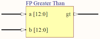
In this tutorial, I have implemented a greater than circuit for simplified floating point number. This circuit compares two simplified floating point number and assert output, gt, only when the first number is larger than the second number. Floating point number in this circuit is not conform to the IEEE 754 standard, hence this format is called simplified floating number.