Ads

Get STM32 tutorial using HAL at $10 for a limited time!

Sunday, January 31, 2016

ARM Cortex-M3 (STM32F103) Tutorial - Unipolar Stepper Motor

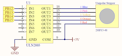
In this tutorial, I will share how control a unipolar stepper motor using STM32F103 microcontroller. If you don't know the basic of the stepper motor, I suggest you to read this article first. To control a stepper motor from microcontroller, we can't directly drive it with GPIO pins because GPIO pins have maximum current that can sink or source from it. To overcome this problem, we can use driver circuit. The driver circuit for unipolar stepper motor can be built by using 4 transistors to drive large current every 4 wires of a stepper motor. It also can be built with ULN2003 IC. This is the circuit for driving a unipolar stepper motor from microcontroller by using ULN2003 IC:


In this tutorial, I will use 28BYJ-48 stepper motor. This motor is very cheap and it also comes with driver module based on ULN2003 IC. This motor runs with 5V supply and has gear inside. The gear reduction ratio is approximately 64:1. If you search from internet, other people say that the gear reduction ratio is actually 63.68395:1.
 

Friday, January 29, 2016

Basic of Stepper Motors

A stepper motor is an electromechanical device which converts electrical pulses into discrete mechanical movements. The shaft of this motor is rotates in discrete step increment when electrical pulses are applied in a proper sequence. Every discrete step of a stepper motor is measured in degree (it can be 1.8° or even smaller depends on the stepper motor type and stepping technique).


This kind of movement is different from DC motors. DC motors is rotates continuously when there is a voltage applied to it and stops when the voltage removed. When the voltage applied to DC motors reversed, the rotation is also reversed. For the stepper motor, we can change the direction of the shaft rotation by reverse the sequence of the applied pulses. The speed of stepper motor shaft rotation is directly related to the frequency input of the pulses. The length of rotation of the stepper motor is directly related to the number of pulses applied.

Sunday, January 10, 2016

ARM Cortex-M3 (STM32F103) Tutorial - System Timer - Delay Function

In this tutorial, I will share how to use system timer (SysTick) for making delay functions. SysTick is a basic countdown timer. SysTick can be used by an operating system to ease porting from another platform. SysTick can be polled by software or can be configured to generate an interrupt. To use SysTick we can reload a value to the reload value register. SysTick reload value register supports value between 0 - 0x00FFFFFF (24-bit).

SysTick can be configured through the 4 registers:


Saturday, January 2, 2016

ARM Cortex-M3 (STM32F103) Tutorial - GPIO - Read Push Button/Switch

In this tutorial, I will explain how to use STM32F103 GPIO peripheral for read input from push button. GPIO (General Purpose Input Output) on STM32F103 can be configure to 4 different modes (input mode, output mode, analog input mode, alternate function mode). For read input from push button, we need to configure GPIO in digital input mode.


STM32F013 has 3 input mode (digital input): input with internal pull-up, input with internal pull-down, and input floating. The logic voltage of STM32 microcontroller is 3.3V, so the logic voltage for GPIO input pins is also 3.3V, but there are several pins that have 5V tolerant. So, we can input 5V logic level to this 5V tolerant input pins. This table below shows I/O voltage level on STM32F103 input pins.

Friday, January 1, 2016

ARM Cortex-M3 (STM32F103) Tutorial - GPIO - Control LED On/Off

In this tutorial, I will explain how to use STM32F103 GPIO peripheral for controlling a LED. GPIO (General Purpose Input Output) on STM32F103 can be configure to 4 different modes (input mode, output mode, analog input mode, alternate function mode). For controlling LED on/off from GPIO, we need to configure GPIO in output mode.


There are 2 output modes on STM32F103. Their modes are output open drain and output push-pull. The logic voltage of STM32F103 is 3.3V, so their port bit output voltage is 3.3V. This is the characteristic of I/O port bit when configured as output mode: