Ads

Get STM32 tutorial using HAL at $10 for a limited time!

Sunday, August 30, 2015

STM32F4 Discovery Tutorial 10 - PWM

In this tutorial, I will share how to use PWM on STM32F4 Discovery board. PWM (Pulse Width Modulation) is a technique for generating analog voltage (average value) by using microcontroller's digital outputs. PWM is used in DC motor speed control, servo motor control, dimming LED, audio generation and many more.


PWM signal is a modulated digital logic (0 and 1). PWM signal have a duty cycle. Duty cycle is measured in percentage. The percentage of duty cycle is calculated from time of a digital signal is on over period of time.


STM32F4 Discovery Tutorial 9 - Timer Interrupt

In this tutorial, I will share how to generate interrupt every given interval using timer on STM32F4 Discovery board. For example project, we will make orange LED toggle every 500ms interval using TIM2. In the main program we will toggle blue LED every 2500ms (blue LED toggling will not using timer interrupt, but just use delay function).

First, we write code for initialize timer. We will use TIM2. This is the block diagram for configuring the timer clock:


void TIM_INT_Init()
{
    // Enable clock for TIM2
    RCC_APB1PeriphClockCmd(RCC_APB1Periph_TIM2, ENABLE);

    // TIM2 initialization overflow every 500ms
    // TIM2 by default has clock of 84MHz
    // Here, we must set value of prescaler and period,
    // so update event is 0.5Hz or 500ms
    // Update Event (Hz) = timer_clock / ((TIM_Prescaler + 1) * 
    // (TIM_Period + 1))
    // Update Event (Hz) = 84MHz / ((4199 + 1) * (9999 + 1)) = 2 Hz
    TIM_TimeBaseInitTypeDef TIM_TimeBaseInitStruct;
    TIM_TimeBaseInitStruct.TIM_Prescaler = 4199;
    TIM_TimeBaseInitStruct.TIM_Period = 9999;
    TIM_TimeBaseInitStruct.TIM_ClockDivision = TIM_CKD_DIV1;
    TIM_TimeBaseInitStruct.TIM_CounterMode = TIM_CounterMode_Up;

    // TIM2 initialize
    TIM_TimeBaseInit(TIM2, &TIM_TimeBaseInitStruct);
    // Enable TIM2 interrupt
    TIM_ITConfig(TIM2, TIM_IT_Update, ENABLE);
    // Start TIM2
    TIM_Cmd(TIM2, ENABLE);

    // Nested vectored interrupt settings
    // TIM2 interrupt is most important (PreemptionPriority and 
    // SubPriority = 0)
    NVIC_InitTypeDef NVIC_InitStruct;
    NVIC_InitStruct.NVIC_IRQChannel = TIM2_IRQn;
    NVIC_InitStruct.NVIC_IRQChannelPreemptionPriority = 0;
    NVIC_InitStruct.NVIC_IRQChannelSubPriority = 0;
    NVIC_InitStruct.NVIC_IRQChannelCmd = ENABLE;
    NVIC_Init(&NVIC_InitStruct);
}

Saturday, August 29, 2015

STM32F4 Discovery Tutorial 8 - External Interrupt

In this tutorial, I will share how to use external interrupt on STM32F4 Discovery. STM32F4 has 23 external interrupt. These external interrupt lines is consist of 2 sections. First sections (line0 to line15) is for external interrupt from GPIO pins (P0 to P15). The other section is for peripherals events (RTC, Ethernet, USB).

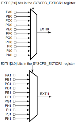
We can use 16 external interrupt line (line0 to line15) to detect external event from GPIO pins. Each pin from all GPIO port is connected to each external interrupt line with the same number.
  • PA0, PB0, PC0 and so on, are multiplexed to line0. So you can only configure one of these pins to connect to line0 interrupt.
  • PA0 and PA8 are multiplexed to different line. So you can configure these pins to use external interrupt at the same time. Because PA0 is connected to line0 and PA8 is connected to line8.