The floating point format is utilized for representing a real number (number with a fractional component). Integer is a number without a fractional component. For example, 0, -2, and 168 are integers, while 12.25, 1/3, and π are real numbers.
In this tutorial, I have implemented a circuit for conversion between simplified floating point and signed integer number. The floating point format for this circuit is 13-bit like in the previous tutorial. The integer is in the 8-bit sign magnitude format. In the sign magnitude format, the MSB is a sign bit, while the other bits is the magnitude. For example, 100000012 is -110 and 000000012 is 110.

An integer to floating point conversion circuit converts an 8-bit integer input to a normalized 13-bit floating point output. A floating point to integer circuit reverses the operation. Since the range of a floating point number is much larger, conversion may lead to the underflow condition (i.e. the magnitude of the converted number is smaller than 000000012) or the overflow condition (i.e. the magnitude of the converted number is larger than 011111112). This experiment is taken from this book: FPGA Prototyping by Verilog Examples by Pong P. Chu. You can learn the detail explanation about this 13-bit floating point format from that book.
This is the code for integer to floating point conversion circuit using behavioral modeling:
module int_to_fp
    (
        input wire [7:0] int_in,
        output reg [12:0] fp_out
    );

    // Signal declaration
    localparam N_BIT = 8;
    reg [6:0] int_mag;
    reg [3:0] fp_exp;
    reg [7:0] fp_frac;
    reg [3:0] lead0;

    // Body
    always @*
    begin
        int_mag[6:0] = int_in[6:0];

        // Get floating point exponent
        if (int_mag[6])
            fp_exp = 4'o7;
        else if (int_mag[5])
            fp_exp = 4'o6;
        else if (int_mag[4])
            fp_exp = 4'o5;
        else if (int_mag[3])
            fp_exp = 4'o4;
        else if (int_mag[2])
            fp_exp = 4'o3;
        else if (int_mag[1])
            fp_exp = 4'o2;
        else if (int_mag[0])
            fp_exp = 4'o1;
        else
            fp_exp = 4'o0;

        // Get floating point fraction by shifting
        // int magnitude according to leading 0
        lead0 = N_BIT - fp_exp;
        fp_frac = int_mag << lead0;

        // Form output
        fp_out[12] = int_in[7];  // Sign
        fp_out[11:8] = fp_exp[3:0];
        fp_out[7:0] = fp_frac[7:0];
    end

endmodule
This is the example calculation for that code. Assume that the input is -3610 (101001002) and the output will be 1 0110 1001 00002 (-0.5625 * 26). To get the exponent we can use the method like we use for priority encoder circuit. To get the normalized fraction (MSB must be 1), we have to remove the leading zero from 001001002, which is has 2 leading zero. We can calculate the leading zero with this formula: N_BIT - exponent (8-6=2). The sign bit is the same in integer as well as in floating point, so we can copy the sign bit.
This is the code for verify this circuit:
This is the code for verify this circuit:
`timescale 1 ns/10 ps

module int_to_fp_tb;
    // Signal declaration
    reg [7:0] int_in_test;
    wire [12:0] fp_out_test;

    // Instantiate the circuit under test
    int_to_fp uut (.int_in(int_in_test), .fp_out(fp_out_test));

    // Test vector generator
    initial
    begin
        int_in_test = 8'b00000000; // +0
        # 200;
        int_in_test = 8'b10000000; // -0
        # 200;
        int_in_test = 8'b00000001; // +1
        # 200;
        int_in_test = 8'b10000001; // -1
        # 200;
        int_in_test = 8'b00000010; // +2
        # 200;
        int_in_test = 8'b10000010; // -2
        # 200;
        int_in_test = 8'b00100100; // +36
        # 200;
        int_in_test = 8'b10100100; // -36
        # 200;
        int_in_test = 8'b01111111; // +127
        # 200;
        int_in_test = 8'b11111111; // -127
        # 200;

        // Stop simulation
        $stop;
    end

endmodule
This is the waveform result from this circuit: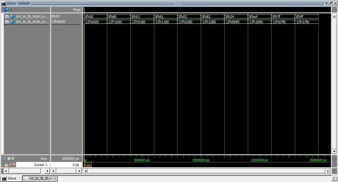
This the code for floating point to integer conversion circuit using behavioral modeling:
module fp_to_int
    (
        input wire [12:0] fp_in,
        output reg [7:0] int_out,
        output reg uf, of
    );

    // Signal declaration
    localparam N_BIT = 8;
    reg [3:0] fp_exp;
    reg [7:0] fp_frac;
    reg [7:0] int_mag;
    reg [3:0] lead0;

    // Body
    always @*
    begin
        fp_exp = fp_in[11:8];
        fp_frac = fp_in[7:0];

        // Default value
        uf = 1'b0;
        of = 1'b0;

        if (fp_frac == 8'b00000000)  // Zero (frac = 0)
            int_mag = 8'b00000000;
        else if (fp_exp < 4'b0001)  // Underflow (exp < 1)
            begin
                int_mag = 8'b00000000;
                uf = 1'b1;
            end
        else if (fp_exp > 4'b0111)  // Overflow (exp > 7)
            begin
                int_mag = 8'b11111111;
                of = 1'b1;
            end
        else
            begin
                // Get int magnitude by adding
                // leading 0 to floating point fraction
                lead0 = N_BIT - fp_exp;
                int_mag = fp_frac >> lead0;
            end

        // Form output
        int_out[7] = fp_in[12];  // Sign
        int_out[6:0] = int_mag[6:0];
    end

endmodule
In addition to floating point input and integer output signal, there are also uf and of signals for underflow and overflow condition respectively. The behavior of this circuit has 3 special case:
- When the floating point fraction is 0, then the magnitude of signed integer is also 0.
- When the floating point exponent is smaller than 1, then the magnitude of signed integer is 0 and the underflow output is asserted.
- When the floating point exponent is larger than 7, then the magnitude of signed integer is 127 and the overflow output is asserted. We can convert fraction bit to integer magnitude by adding the leading zero. The leading zero can be obtained by using this formula: N_BIT - exponent. The sign bit is the same in floating point as well as in integer, so we can copy the sign bit.
For example, we want to convert -36 from floating point format: -0.5625 * 26 (1 0110 1001 00002) to signed integer format: 101001002. By adding the leading zero (2 leading zero) to fraction bit we can get the magnitude of integer which is 0010 01002. The sign bit is copied form MSB of floating point input, then this bit will replace the MSB of integer magnitude, so the result is 101001002.
This is the code for verify this circuit:
This is the code for verify this circuit:
module fp_to_int_tb;
    // Signal declaration
    reg [12:0] fp_in_test;
    wire [7:0] int_out_test;
    wire uf_test, of_test;

    // Instantiate the circuit under test
    fp_to_int uut
        (.fp_in(fp_in_test), .int_out(int_out_test),
        .uf(uf_test), . of(of_test));

    // Test vector generator
    initial
    begin
        fp_in_test = 13'b0000000000000; // +0.00000000 * 2^0 (+0)
        # 200;
        fp_in_test = 13'b1000000000000; // -0.00000000 * 2^0 (-0)
        # 200;
        fp_in_test = 13'b0000010000000; // +0.10000000 * 2^0 (+0.5)
        # 200;
        fp_in_test = 13'b1000010000000; // -0.10000000 * 2^0 (-0.5)
        # 200;
        fp_in_test = 13'b0000011111111; // +0.11111111 * 2^0 (+0.999)
        # 200;
        fp_in_test = 13'b1000011111111; // -0.11111111 * 2^0 (-0.999)
        # 200;
        fp_in_test = 13'b0000110000000; // +0.10000000 * 2^1 (+1)
        # 200;
        fp_in_test = 13'b1000110000000; // -0.10000000 * 2^1 (-1)
        # 200;
        fp_in_test = 13'b0000111110000; // +0.11110000 * 2^1 (+1.875)
        # 200;
        fp_in_test = 13'b1000111110000; // -0.11110000 * 2^1 (-1.875)
        # 200;
        fp_in_test = 13'b0001010000000; // +0.10000000 * 2^2 (+2)
        # 200;
        fp_in_test = 13'b1001010000000; // -0.10000000 * 2^2 (-2)
        # 200;
        fp_in_test = 13'b0011010010000; // +0.10010000 * 2^6 (+36)
        # 200;
        fp_in_test = 13'b1011010010000; // -0.10010000 * 2^6 (-36)
        # 200;
        fp_in_test = 13'b0011111111110; // +0.11111110 * 2^7 (+127)
        # 200;
        fp_in_test = 13'b1011111111110; // -0.11111110 * 2^7 (-127)
        # 200;
        fp_in_test = 13'b0100010000000; // +0.10000000 * 2^8 (+128)
        # 200;
        fp_in_test = 13'b1100010000000; // -0.10000000 * 2^8 (-128)
        # 200;
        fp_in_test = 13'b0111111111111; // +0.11111111 * 2^15 (+32460)
        # 200;
        fp_in_test = 13'b1111111111111; // -0.11111111 * 2^15 (-32460)
        # 200;

        // Stop simulation
        $stop;
    end

endmodule
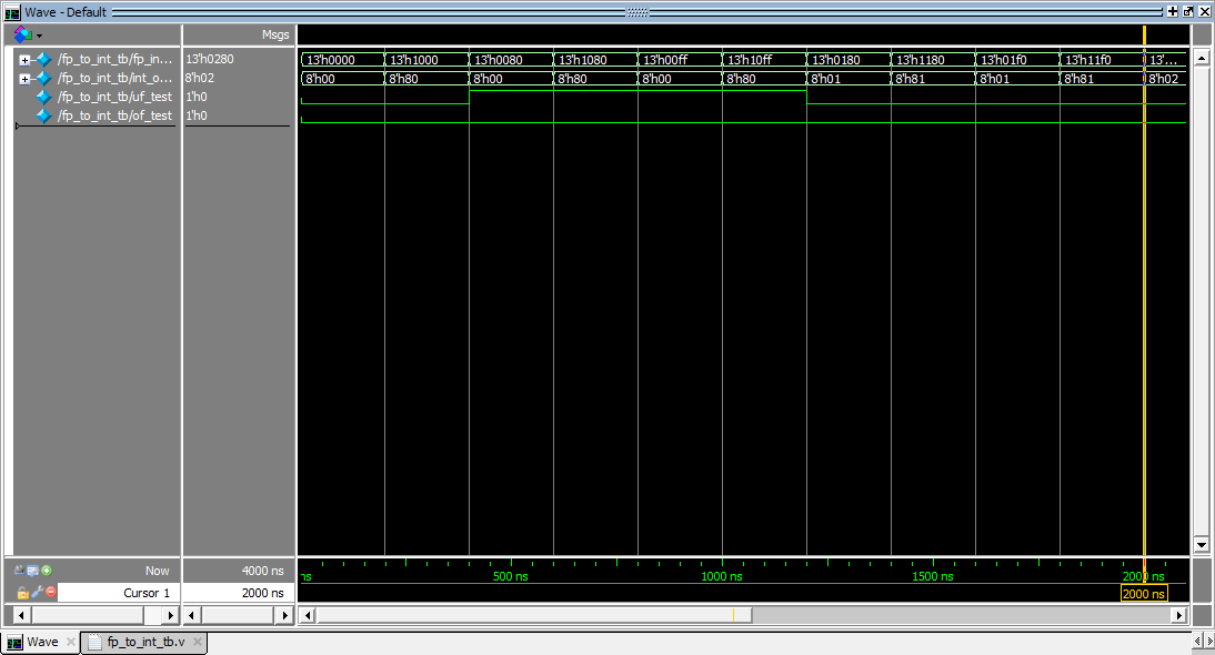
This is the waveform result from this circuit:

You can download the project file of this circuit from my repository.
Do you realize there is a 12 word sentence you can say to your man... that will induce intense emotions of love and instinctual attractiveness to you buried within his chest?
ReplyDeleteBecause deep inside these 12 words is a "secret signal" that triggers a man's instinct to love, idolize and look after you with his entire heart...
12 Words Will Fuel A Man's Love Response
This instinct is so built-in to a man's mind that it will make him try harder than ever before to make your relationship the best part of both of your lives.
Matter-of-fact, fueling this powerful instinct is so mandatory to having the best ever relationship with your man that once you send your man one of the "Secret Signals"...
...You'll immediately find him open his heart and soul for you in such a way he never expressed before and he'll distinguish you as the only woman in the universe who has ever truly understood him.
It is actually a great and useful piece of information.
ReplyDeleteI'm happy that you simply shared this helpful information with us. Please stay us up to date like this. Thank you for sharing."
data logger Distributor
kuşadası
ReplyDeletemilas
çeşme
bağcılar
adıyaman
SF3T