In this tutorial, I will share how control a unipolar stepper motor
using STM32F103 microcontroller. If you don't know the basic of the
stepper motor, I suggest you to read this article first. To control a
stepper motor from microcontroller, we can't directly drive it with GPIO
pins because GPIO pins have maximum current that can sink or source
from it. To overcome this problem, we can use driver circuit. The driver
circuit for unipolar stepper motor can be built by using 4 transistors
to drive large current every 4 wires of a stepper motor. It also can be
built with ULN2003 IC. This is the circuit for driving a unipolar
stepper motor from microcontroller by using ULN2003 IC:

In this tutorial, I will use 28BYJ-48 stepper motor. This motor is very cheap and it also comes with driver module based on ULN2003 IC. This motor runs with 5V supply and has gear inside. The gear reduction ratio is approximately 64:1. If you search from internet, other people say that the gear reduction ratio is actually 63.68395:1.

There are 2 common mode that can be used for control stepper motor: full step and half step. Actually there is 1 more mode that can be used for control stepper motor in more advanced ways. That mode is called micro step. But in this tutorial, I will explain only full step and half step.
We know that the stepper motor is controlled by giving a sequence of electrical pulse. That electrical pulses is applied to 4 wires of stepper motor. Each electrical pulse is consist of 4-bits. We can applied these pulses to 4 wires by 4-bits of GPIO pins. The full step mode has a sequence of electrical pulses that consist of 4 different pulses. Every 1 sequence is equivalent to 4 steps of movement. So, 1 pulse is equivalent to 1 step movement. This is the sequence of full step mode:

One step movement of this motor in full step mode is 11.25°. By applying these sequence once, the internal shaft of stepper motor will move 4x11.25°=45°. To rotate the internal shaft of stepper motor 1 revolution, we need 360°/45°=8 sequence (32 steps). But the actual shaft of this motor is geared with 64:1 gear ratio. That means every actual shaft rotates 1 revolution, the internal shaft must rotates 64 revolution. So, to rotate the actual shaft 1 revolution, we need 32x64=2048 steps. To move stepper motor 2048 steps, we can applied the sequence 512 times (because 1 sequence is 4 step movement).
This is the code for rotating the actual shaft of stepper motor 1 revolution clockwise:
// One revolution CW using full step mode
for (cycle = 0; cycle < 512; cycle++)
{
    GPIO_Write(GPIOB, 0x1000);
    delay(5);
    GPIO_Write(GPIOB, 0x2000);
    delay(5);
    GPIO_Write(GPIOB, 0x4000);
    delay(5);
    GPIO_Write(GPIOB, 0x8000);
    delay(5);
}
Between each pulse in a sequence, we need to add delay, because the stepper motor is work much slower compared to the execution time of a microcontroller to execute one line of code. This delay allow stepper to move 1 step before we apply next pulse. This delay is directly related to rotation speed of the shaft. The smaller delay value will give faster rotation speed. We can reverse the direction of the shaft rotation by reversing the sequence applied.
// One revolution CCW using full step mode
for (cycle = 0; cycle < 512; cycle++)
{
    GPIO_Write(GPIOB, 0x8000);
    delay(5);
    GPIO_Write(GPIOB, 0x4000);
    delay(5);
    GPIO_Write(GPIOB, 0x2000);
    delay(5);
    GPIO_Write(GPIOB, 0x1000);
    delay(5);
}
This is the full code for rotates the stepper motor 1 revolution clockwise and the 1 revolution counter-clockwise:
#include "stm32f10x.h"
#include "stm32f10x_rcc.h"
#include "stm32f10x_gpio.h"

void delay(unsigned int nCount);
GPIO_InitTypeDef GPIO_InitStruct;
int cycle = 0;

int main(void)
{
    RCC_APB2PeriphClockCmd(RCC_APB2Periph_GPIOB, ENABLE);

    GPIO_InitStruct.GPIO_Pin = GPIO_Pin_12 | GPIO_Pin_13 |
        GPIO_Pin_14 | GPIO_Pin_15;
    GPIO_InitStruct.GPIO_Speed = GPIO_Speed_2MHz;
    GPIO_InitStruct.GPIO_Mode = GPIO_Mode_Out_PP;
    GPIO_Init(GPIOB, &GPIO_InitStruct);

    // One revolution CW using full step mode
    for (cycle = 0; cycle < 512; cycle++)
    {
        GPIO_Write(GPIOB, 0x1000);
        delay(5);
        GPIO_Write(GPIOB, 0x2000);
        delay(5);
        GPIO_Write(GPIOB, 0x4000);
        delay(5);
        GPIO_Write(GPIOB, 0x8000);
        delay(5);
    }

    delay(1000);

    // One revolution CCW using full step mode
    for (cycle = 0; cycle < 512; cycle++)
    {
        GPIO_Write(GPIOB, 0x8000);
        delay(5);
        GPIO_Write(GPIOB, 0x4000);
        delay(5);
        GPIO_Write(GPIOB, 0x2000);
        delay(5);
        GPIO_Write(GPIOB, 0x1000);
        delay(5);
    }

    while (1)
    {
    }
}

void delay(unsigned int nCount)
{
    unsigned int i, j;

    for (i = 0; i < nCount; i++)
        for (j = 0; j < 0x2AFF; j++);
}
Half step mode is consist of 8 electrical pulse every 1 sequence. This is the sequence of half step mode:
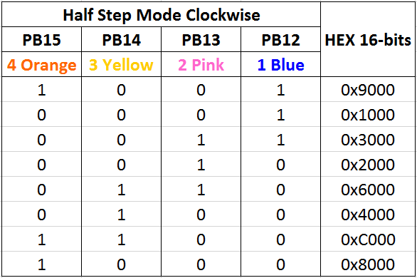
The different between full step and half step is on the step resolution. When you use half step mode, you will get more smaller degree per step movement. In this motor if we use half step mode, you will get 5.625° per 1 step, but the total number of degree per 1 sequence is same (5.625°x8=45°). The effect is the shaft will rotates more smooth.
This is the code for rotates the stepper motor 1 revolution clockwise and the 1 revolution counter-clockwise using half step mode:
This is the code for rotates the stepper motor 1 revolution clockwise and the 1 revolution counter-clockwise using half step mode:
// One revolution CW using half step mode
for (cycle = 0; cycle < 512; cycle++)
{
    GPIO_Write(GPIOB, 0x9000);
    delay(5);
    GPIO_Write(GPIOB, 0x1000);
    delay(5);
    GPIO_Write(GPIOB, 0x3000);
    delay(5);
    GPIO_Write(GPIOB, 0x2000);
    delay(5);
    GPIO_Write(GPIOB, 0x6000);
    delay(5);
    GPIO_Write(GPIOB, 0x4000);
    delay(5);
    GPIO_Write(GPIOB, 0xC000);
    delay(5);
    GPIO_Write(GPIOB, 0x8000);
    delay(5);
}

delay(1000);

// One revolution CCW using half step mode
for (cycle = 0; cycle < 512; cycle++)
{
    GPIO_Write(GPIOB, 0x8000);
    delay(5);
    GPIO_Write(GPIOB, 0xC000);
    delay(5);
    GPIO_Write(GPIOB, 0x4000);
    delay(5);
    GPIO_Write(GPIOB, 0x6000);
    delay(5);
    GPIO_Write(GPIOB, 0x2000);
    delay(5);
    GPIO_Write(GPIOB, 0x3000);
    delay(5);
    GPIO_Write(GPIOB, 0x1000);
    delay(5);
    GPIO_Write(GPIOB, 0x9000);
    delay(5);
}
This is the result:
No comments :
Post a Comment